2002 Buell P3: Electrical 7-69
HOME
20. Remove nut and clamp that secures oil hoses and wiring
harness on right side of motorcycle.
21. Disconnect Neutral Switch bullet connector [172].
22. Disconnect speed sensor connector [65] located in
frame tray on right side.
23. Disconnect side stand switch connector [60] above swing
arm.
24. Disconnect oil pressure switch connector [120].
25. Disconnect rear brake line switch connector [121]
located above swingarm on right side of motorcycle.
26. See Figure 7-99. Unplug flasher relay connector [30] and
starter relay connector [123] located in frame tray on
right hand side.
27. Unplug system relay connector [171] located in frame
tray on left side.
28. See Figure 7-99. Disconnect positive (+) wire from bat-
tery on circuit breaker (upper stud).
29. Disconnect tail lamp/turn signal mini harness connector
[7] located under seat.
30. Unhook fuse block.
31. Note location, and cut two zip ties on wire to frame and
wire on voltage regulator mount. Disconnect voltage reg-
ulator wire and wire attached to frame.
32. Pull main wiring harness out through rear of frame.
INSTALLATION
1. Feed main wiring harness through frame from back to
front.
2. See Figure 7-99. Connect flasher relay connector [30] to
flasher relay and starter relay connector [123] to starter
relay.
3. Connect system relay connector [171] to system relay.
4. Install fuse block.
5. Connect positive (+) wire to circuit breaker. Tighten metal
nut to 15-18 in-lbs. Tighten plastic acorn nut to 1-3 in-
lbs (0.1-0.3 Nm).
6. Feed negative (-) wire across frame and connect to volt-
age regulator mount and frame. Use two cable ties to
secure wires.
7. See Figure 7-98. Mate speed sensor connector [65].
Tuck excess harness into right frame pocket.
8. Connect two blade terminals to stoplight switch above
swingarm.
9. Mate side stand switch connector [60] located above
swingarm. Cable tie wires.
10. Install starter connector [128] located under starter sole-
noid.
11. Install neutral switch bullet connector [172].
12. Install oil pressure switch connector [120] to oil pressure
switch. Route wire around oil pump.
13. Install hose clamp around hoses and oil pressure switch
and neutral switch wires. Secure clamp with new lock-
nut.
14. Attach main wiring harness to T-studs.
15. Feed wire harness through upper tie bar mount in two
bundles.
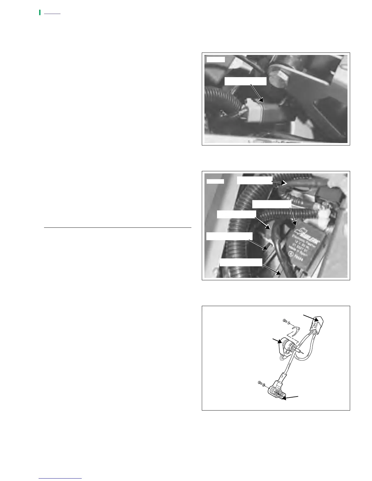
16. See Figure 7-100. Mate TP Sensor/Auto-Enrichener con-
nector [88] and secure with cable tie.
17. Install connector [83] to coil and secure with cable tie.
Figure 7-98. Speed Sensor Connector [65]
Figure 7-99. Flasher Relay Connector [30]
Figure 7-100. TP Sensor/Auto-Enrichener Connector [88]
7819
Connector [65]
7820
Connector [30]
Starter Relay
Flasher Relay
Connector [123]
Positive Wire
a0265x7x
Throttle Position
Sensor
Connector [88]
Auto-Enrichener