M-Series Operator’s Manual 4/9/15
10-53
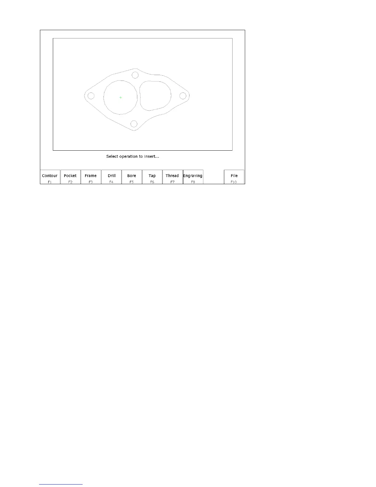
After the zero reference is set the Select Intercon operation menu appears.
This menu allows you to select the type of Intercon operation you wish to create using geometry from the DXF file.
F1 – Contour Convert one or more connected lines and/or arcs to linear and arc operations.
F2 – Pocket Convert a chain of lines and/or arcs to one of the Intercon pocket operations. The type of pocket
depends on the geometry of the selected chain. A chain of arcs will be converted to a circular pocket if all
arcs have the same center point and radius. A chain of four lines forming a rectangle will be converted to a
rectangular pocket. All other chains will be converted into a cleanout operation.
F3 – Frame Create a frame operation that surrounds a chain of lines and/or arcs. The height, width and center of the
chain are used to define the frame.
F4 – Drill Convert one or more points to a drilling operation.
F5 – Bore Convert one or more points to a boring operation.
F6 – Tap Convert one or more points to a tapping operation.
F7 – Thread Convert one or more points to a threading operation.
F8 – Engrave (Optional) Converts the entire file to engraving operations. Choosing this option displays the
engraving menu. Set the options as desired for the engraving. Surface Height is the height of the surface
to be engraved. Clearance Height is the height that the engraving tool will move up to clear the surface.
Depth is the depth of the engraving. Set the Plunge Rate and Feedrate appropriately for the tool and
material.
F10 – File Pressing F10 - File displays the following options:
F1 – Load Load a new DXF file.
F2 - Zero Change the current zero reference.
F3 - Gap Modify the current gap tolerance. Two lines or arcs are connected if the distance between their end points is
less than the gap tolerance.