M-Series Operator’s Manual 4/9/15
10-67
Intercon Tutorial #2
This demonstration will show you how to create a tool path for a part from a blueprint using the Math Help function of
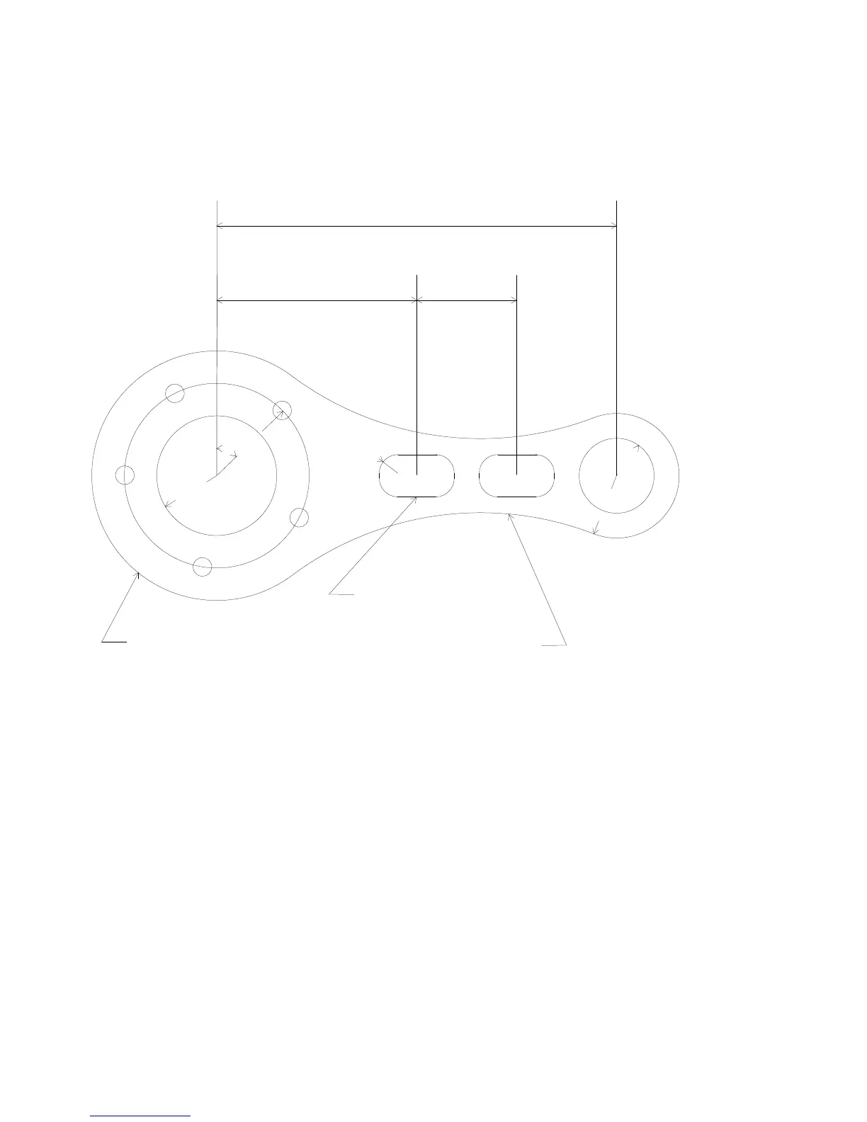
Intercon. The tool path to be created is for the part shown in Figure 1 below.
FIG. 1 - Part to be machined
.
Part Creation
The process of creating a part is called part programming. Each feature of the part will become an operation in your
program. Before beginning, decide where you want the X0 and Y0 reference. For this particular demo, the center of
the Bolt Hole pattern was selected for convenience). Beginning from the Intercon File Menu (press F1 - File if the file
menu is not shown) the following series of keystrokes will describe the step-by-step process of designing the part
shown in Figure 1.
0.1875"
0.3750"
0.6250"
0.6000"
0.9250"
4.0000"
2.0000"
1.0000"
45
0.7500" x 0.4250"
3.1500" R
1.2500" R