M-Series Operator’s Manual 4/9/15 11-5
#, = - User or System Variable reference
The ‘#’ character is used to reference a macro or a user or system variable. For variables that can be written, the ‘=’
is used to assign to them. General purpose user variables are #100 to #149 and #29000 to #31999.
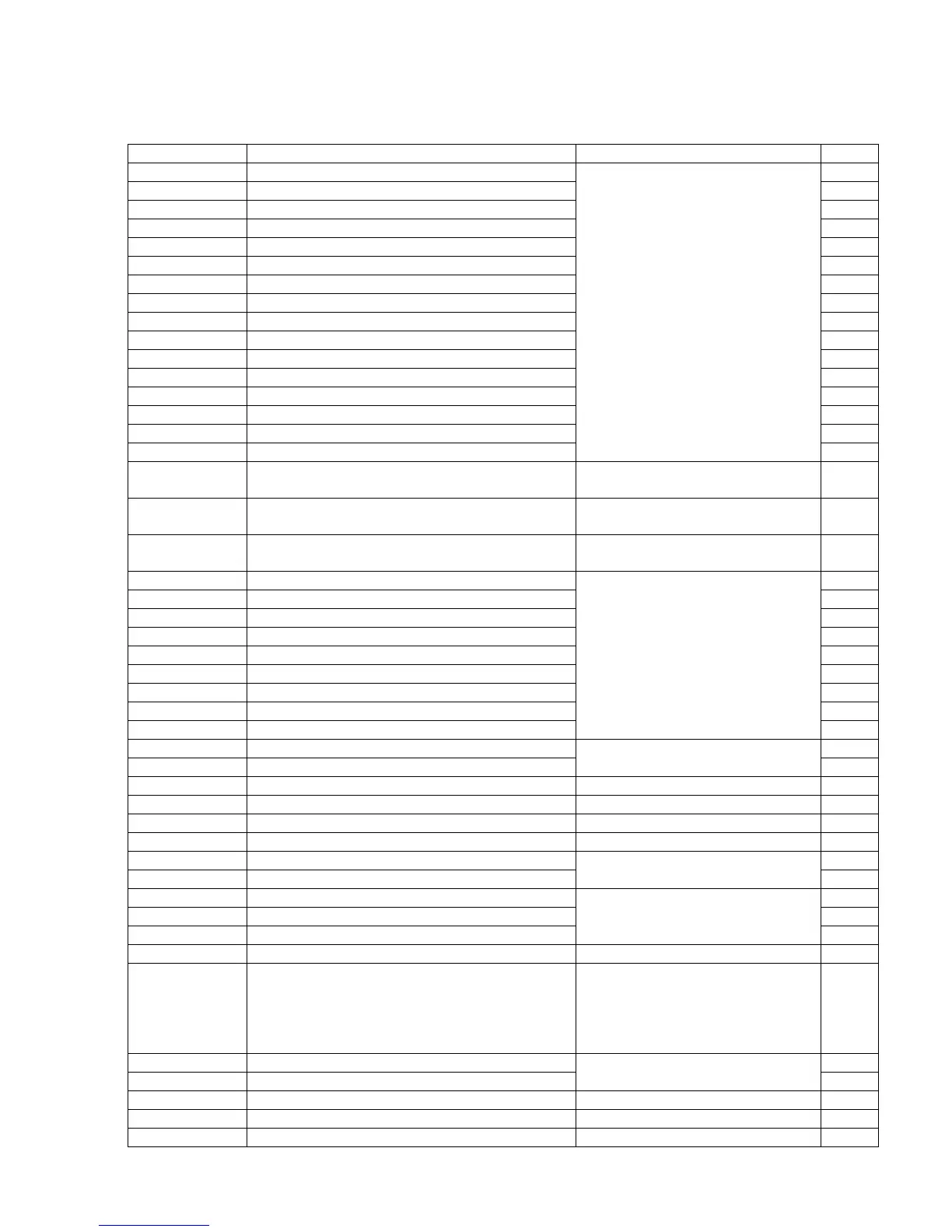
Index Description Returns R/W
1-3 Macro arguments A-C R/W
4-6 Macro arguments I-K (1st set) R/W
7-9 Macro arguments D-F or 2nd set of I-K R/W
10 3rd I (G is invalid) R/W
11 Macro argument H or 3rd J R/W
12 3rd K (L is invalid) R/W
13 Macro argument M or 4th I R/W
14 4th J (N is invalid) R/W
15 4th K (O is invalid) R/W
16 5th I (P is invalid) R/W
17-18 Macro argument Q-R or 5th J-K R/W
19-21 Macro arguments S,T,U or 6th set of I-K R/W
22-24 Macro arguments V,W,X or 7th set of I-K R/W
25-27 Macro arguments Y,Z or 8th set of I-K R/W
28-30 9th set of I-K R/W
31-33 10th set of I-K
The floating point value if defined by
a G65 call, 0.0 otherwise.
These can be used as private, local
variables in any program or
subprogram except in custom macro
M functions. In custom macro M
functions, the macro arguments are
passed in by reference.
R/W
100 - 149 User variables Floating-point value. Initialized to
0.0 at start of job processing
R/W
150 – 159 Nonvolatile user variables Floating-point value saved in
cncm.job.xml file.
R/W
300-399 User string variables. These variables retain their
values until the CNC software is exited
String Literal R/W
2400, 2401-2418
Active WCS, WCS #1-18 CSR angles R/W
2500, 2501-2518
Active WCS, WCS #1-18 Axis 1 values R/W
2600, 2601-2618
Active WCS, WCS #1-18 Axis 2 values R/W
2700, 2701-2718
Active WCS, WCS #1-18 Axis 3 values R/W
2800, 2801-2818
Active WCS, WCS #1-18 Axis 4 values R/W
2900, 2901-2918
Active WCS, WCS #1-18 Axis 5 values R/W
3000, 3001-3018
Active WCS, WCS #1-18 Axis 6 values R/W
3100, 3101-3118
Active WCS, WCS #1-18 Axis 7 values R/W
3200, 3201-3218
Active WCS, WCS #1-18 Axis 8 values
Floating point value
R/W
3901 Parts Cut (Part #) R/W
3902 Parts Required (Part Cnt)
R/W
4001 Move mode 0.0 (rapid) or 1.0 (feed) R
4003 Positioning mode 90.0 (abs) or 91.0 (inc) R
4006 Units of measure 20.0 (inches) or 21.0 (metric) R
4014 WCS 54.0-71.0 (WCS#1-18) R
4109 Feedrate (F) R
4119 Spindle Speed (S)
Floating point value
R
4120 Tool Number (T) R
4121 Current height offset number (H) R
4122 Current diameter offset number (D, mill only)
R
4201 Job processing state 0 = normal, 1 = graph R
4202 Job Search mode 0 = search mode off
1 = searching for line number
2 = searching for block number N__
3 = searching for Tool number
4 = resuming job
R
5021-5028 Machine Position (X=5021, Y=5022, etc.) R
5041-5048 Current Position (X=5041, Y=5042, etc.)
Floating point value
R
9000-9399 Parameter values 0 – 399 See Chapter 14 R
9900-9999 Parameter values 900 – 999 See Chapter 14 R
10000 Mill: Height offset amount, active H Floating point value R/W