M-Series Operator’s Manual 4/9/15
Whenever cutter compensation is applied, the following factors must be taken into account in order to obtain proper
results.
1. The cutter diameter compensation function (G41, G42) must be implemented before the cutter tool reaches the
starting cutting point.
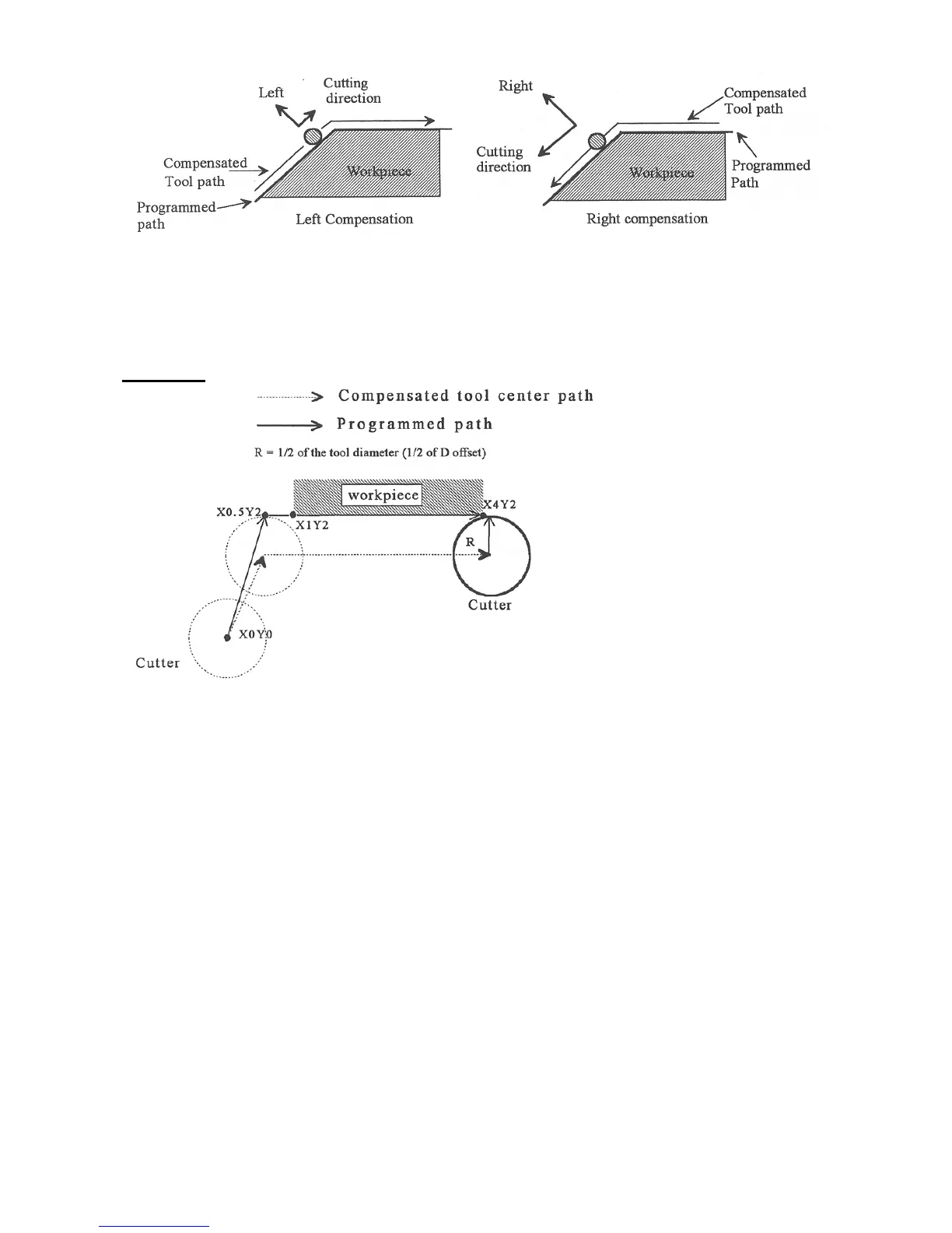
Example 1:
G0X0Y0 ; Rapid tool to X0, Y0
G42 D3 ; Turn cutter compensation on, with a diameter of D3
G0X.5Y2 ; Rapid to X0.5, Y2
G1x4.1Y2 ; Linear cut to X4.1, Y2.
; Cut to X4.1 to clear material.
G40 ; Turn cutter compensation off.
G0X5Y0 ; Rapid to X5, Y0.
You may want to add .1 or .05 inches on the final position for the last cut to clear the material.
NOTE: The diameter compensation statement G42 is placed before G0 X.5 Y2. As a result, the compensation is
applied before the cutter reaches the starting cutting point X.5 Y2.
2. If the cutter is down, then the cutter compensation lead-in must always come from an appropriate direction.
Otherwise, the work piece will be incorrectly cut, and the cutter tool could be damaged. One way to avoid this
problem is by always keeping the cutter above the work piece whenever a transition is being made to a new starting
cutting point. If for some reason this was not possible, then the G-code program should be written so that the cutter
compensation lead-in paths do not interfere with the space occupied by the work piece. Example 2 illustrates a
possible harmful outcome of programming an inappropriate lead-in direction.