M-Series Operator’s Manual 4/9/15
Example 2:
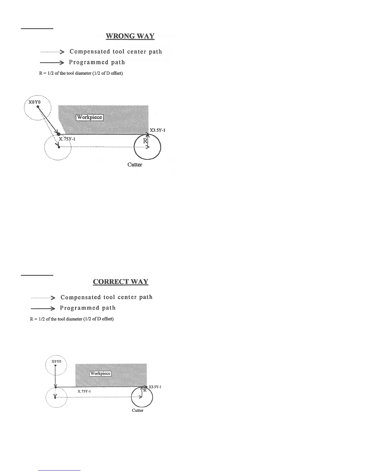
G0 X0Y0 ; Rapid tool to X0, Y0
G42 D5 ; Turn cutter compensation on, with a diameter of D5
G1 X.75Y-1 F5 ; Linear move to X0.75, Y-1. (Notice this damages the
; corner of the work piece)
X3.6 ; move X to 3.6
G40 ; Turn cutter compensation off.
G0 X4Y-2 ; Rapid to X4, Y-2
* NOTE: This problem could have been avoided by selecting a transitional point between X0 Y0 and X.75 Y-1. A
transitional point such as X-1 Y-1 would properly modify the lead-in path, keeping the cutter from damaging the
corner of the work piece. Example 3 shows the correct way of performing this operation.
Example 3: