M-Series Operator’s Manual 4/9/15
Example:
(Part surface height is Z = 0, initial tool position is X.50 Y1.0 Z.625. Drill 0.50 deep hole at X1.0 Y1.0; clearance
height (R) is 0.10 above surface.)
Absolute Incremental
G90 G91
G81 X1 Y1 R.1 Z-.5 G81 X.5 Y0 R-.525 Z-.6
G80 G80
* NOTE for Articulated Head machines configured with the TWCS feature enabled via Parameter 166:
If the currently selected WCS is non-TWCS (TWCS = No) and the B axis is at an angle other than 0, then you
cannot use the regular Canned Cycle G-codes G73, G74, G76, G81, G82, G83, G84, G85, G89. You must use the
Compound Canned Cycle G-codes G173, G174, G176, G181, G182, G183, G184, G185, G189 instead. Using
regular Canned Cycle G-codes when the B axis is not 0 is an error and will cancel the job. See “G173, G174... –
Compound Canned Cycles” later in this chapter for more information about this subject. See Chapter 14 for more
information about Parameter 166.
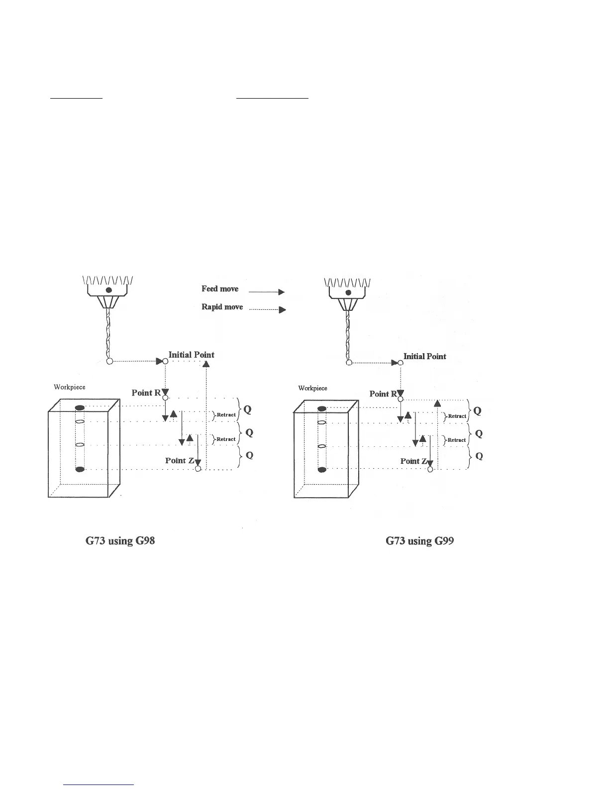
G73 - High Speed Peck Drilling
G73 is the peck drilling cycle. The hole is drilled in a series of moves: down a distance Q at a given feedrate, up
the retract distance at the rapid rate, and then down again at the given feedrate. The retract amount is set with G10
as shown in the example below.
Example:
G90 ; Absolute positioning
G01 X3.00 Y1.50 Z.5 ; G01 mode before canned cycle
G98 ; Set for initial point return
G10 P73 R.1 ; Sets the retract amount to .1
G73 X3.250 Y1.75 Z-.650 R.1 Q0.325 F3 ; Peck drill at X3.25 Y1.75
X4.5 Y3.5 ; Peck drill at X4.5 Y3.5
G80 ; Cancel canned cycle, return
; to G01