M-Series Operator’s Manual 4/9/15
Bit-mapped parameters
Certain control parameters are defined by bit-mapped values. In order to change these parameters you must
understand how bit mapping works. A bit-mapped parameter is stored as a number, representing a 16-bit
value in the control. If a certain bit needs to be turned on, that bit’s binary value must be added to the
parameter value, if the bit needs turned off, its binary value must be subtracted from the parameter value.
The values for each of the 16 bits’ can be seen in the table below.
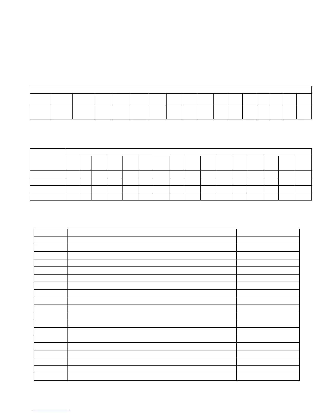
Bit-Mapped Parameter Bits
Bit
15 14 13 12 11 10 9 8 7 6 5 4 3 2 1 0
Value
32768
16384
8192
4096
2048
1024
512 256
128
64 32 16 8 4 2 1
To set bit-mapped parameters simply add together the bit values that you need to have enabled.
Examples:
Bit number and settings Parameter
value
15 1
4
13 12 11 10 9 8 7 6 5 4 3 2 1 0
0 X X X X X X X X X X X X X X X X
1 X X X X X X X X X X X X X X X ON
11 = 8+2+1
X X X X X X X X X X X X ON X ON ON
24 = 16+8 X X X X X X X X X X X ON ON X X X
The following parameters are currently defined:
Parameter Definition Default setting
0 E-Stop PLC Bit 0
1 Y jog key orientation 0
2 G-Code Interpretation Control and Slaving Rotary axis feedrate 0
3 Modal Tool and Height Offset Control 0
4 Remote File Loading Flag & Advanced File Ops 0
5 Suppress Machine Home Setup 0
6 Auto Tool Changer Installed 0
7 Display Colors 0
8 Available Coolant System(s) 2
9 Display Language 0
10 Macro M-Function Control/Probe Stop Handling 0
11 Touch Probe PLC Input 15
12 Touch Probe Tool Number 0
13 Probing Recovery Distance 0.05” / 1.27 mm
14 Fast Probing Rate 10 ipm or 254 mm/min
15 Slow Probing Rate 1 ipm or 25.4 mm/min
16 Probing Search Distance 10” / 254 mm
17 Tool Detector Reference Number 0
18 PLC Input Spindle Inhibitor 0