M-Series Operator’s Manual 4/9/15
Parameter 0 – E-Stop PLC Bit
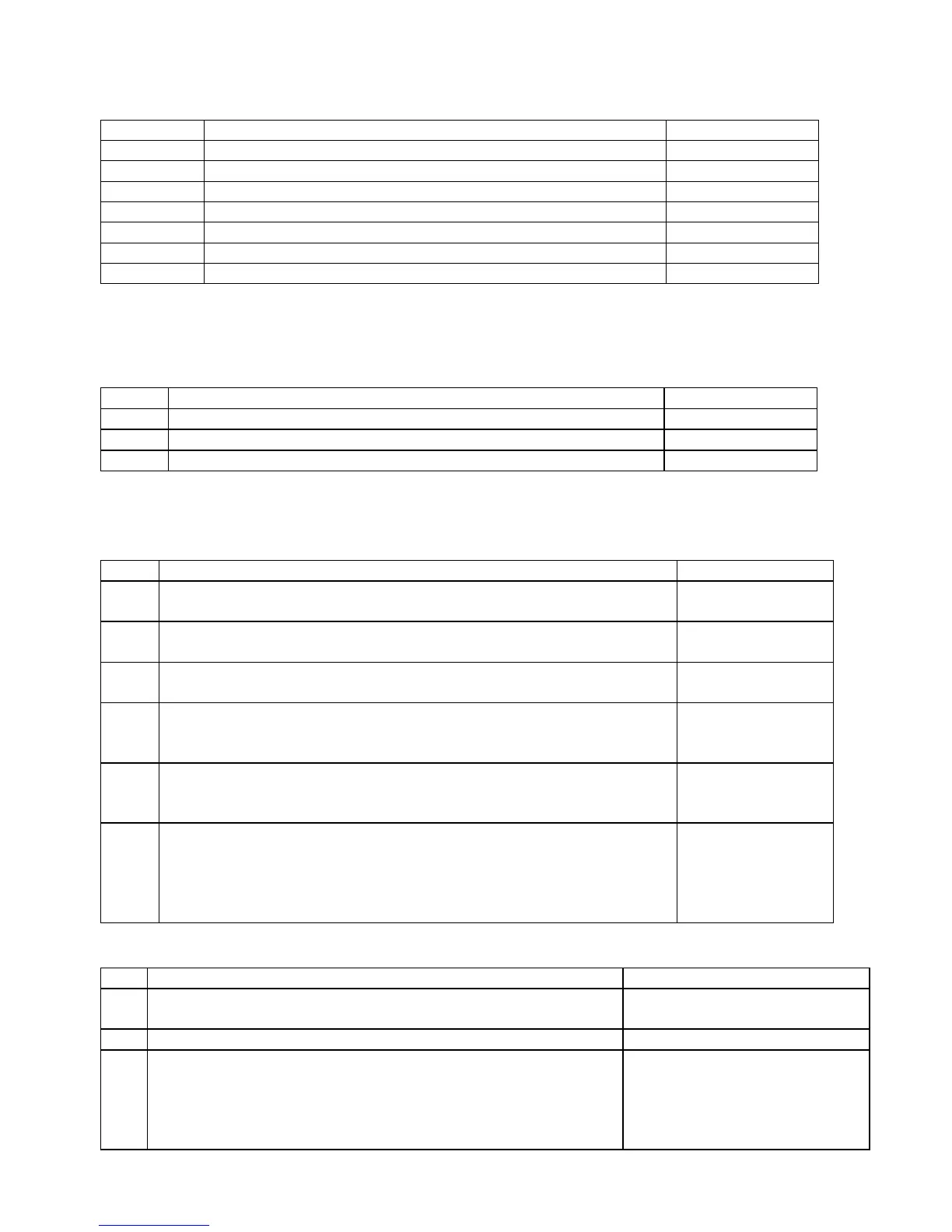
This parameter specifies the PLC bit to which the physical Emergency Stop switch is connected. It is mainly used for
ATC applications that use custom PLC messages. See table below for examples.
PLC Type ESTOP Input on PLC Parameter Value
GPIO4D Input 11 -11
ALLINONE
Input 11 -11
OAK Input 11 -11
RTK2/3/4 Input 11 -11
PLCIO2 Input 11 -11
DC3IO Input 11 -11
Servo3IO Input 1 1
Parameter 1 – Y jog key orientation
This parameter is a 3-bit field where bit 0 is not used in the mill software. Bit 1 sets the direction of movement for the
Y+ and Y- jog keys and bit 2 will swap the X and Y jog keys. This should always be set to 0 except for very special
applications. Note: PLC program interaction is needed for these features.
Bit Function Description Parameter Value
0 Not Used
1 Flip direction of Y jog keys? Yes=2, No=0
2 Exchange X axis and Y-axis jog keys? Yes=4, No=0
Parameter 2 - G-code Interpretation Control and Slaving Rotary axis feedrate
This parameter is a bit field that controls optional interpretation of several G-codes. The following table shows the
functions performed by the value entered in this parameter:
Bit Function Description Parameter Value
0 Arc centers I, J, K are absolute in G90 mode? Yes = 1
No = 0
1 Allow Z being specified alone to be sufficient to trigger execution of a
canned tapping or drilling cycle to be executed?
Yes = 2
No = 0
2 Interpret dwell times associated with G4, G74, G82, G84, and G89 as
milliseconds rather than seconds?
Yes = 4
No = 0
3 Slaving rotary axis feedrate to non-rotary axis feedrate
Note that this feature has no effect for movement commands handled by
Smoothing (when parameter 220=1).
Yes = 8
No = 0
4 Selects the center for scale, mirror and rotate. By default the center will
be 0,0,0. Add 16 to this parameter to make the center of scale, mirror and
rotate the current position.
Yes = 16
No = 0
5 Prevent rotary-only moves (rotary axis by itself on a line of G-code) from
acquiring a remembered slaved rotary feedrate previously set by a
previous line of G-code containing a rotary and non-rotary together.
Note that this feature has no effect for movement commands handled by
Smoothing (when parameter 220=1).
Yes = 32
No = 0
Parameter 3 - Modal Tool and Height Offset Control
Bit Meaning Parameter Value
0 Tool and Height Offset numbers, T and H, will be reset upon job
completion (and not remain modal and active between jobs).
Reset upon job completion = 1,
Remain modal between jobs = 0
1 Reference tool position is set to Z home. Yes = 2 No = 0
2 Tool Height Offset Retention option. This option prevents the
current tool height offset from being turned off when the user enters
the Tool Height Offset menu. Additionally, this option will cause
the H height offset to be set to match the tool number when an Auto
Tool Change is performed (via F7 ATC) in the Offset Library.
Turn on Tool Height Offset
Retention option = 4, No = 0