M-Series Operator’s Manual 4/9/15
Parameter 11 – DP4 PLC Input Number and Contact State
This parameter is used for the PLC input number that is used by the DP4 Touch Probe. Allowable range is a single
value, +/- 1 to 240 and 50001 to 51312. A Positive number indicates Closed on contact and a negative number
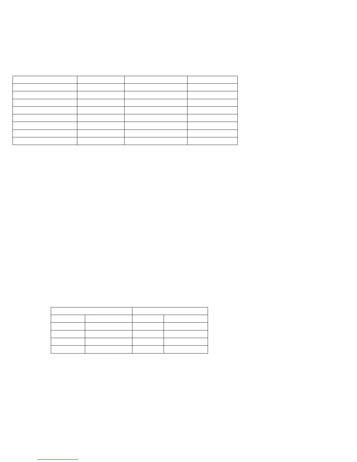
indicates Open on contact. A list of default settings for different console types are listed below.
NOTICE
Changing this parameter can cause damage to your probe. You should contact your
Dealer or Local Tech Representative before any modifications are made.
Console Type/Model Input Number PLC Type/Model Input Number
M39 15 DC3IO 14
M39s 14 RTK3 14
M400 15 Servo3IO 2
M400s 14 PLCIO2 15
M15-10 2 15/15 15
M400 ATC (RTK3) 14 RTK2 15
M400 ATC (PLCIO2) 15 Koyo ATC 1
MPU11 50769
Parameter 12 – Touch Probe Tool Number
This parameter is the tool number of the DP4 probe. Allowable range is 0 through 200. By default the value is 10. This
is used to look up the length offset and tip diameter of the probe in the Tool Offset Library.
Parameter 13 – Recovery Distance
This parameter is the distance that the probe moves off a surface after initial contact (only during probing cycles),
before returning to the surface to take a recorded reading.
For DSP Probes: This parameter is used for failed DSP windows. On a failed window, the DSP probe will retract this
distance before retrying.
Parameter 14 – Fast Probing Rate
The fast probing rate is used for positioning moves and initial surface detection, and is determined by the machines
response time and the permitted probe deflection. The default is 10 in/min. This is a very conservative feedrate, in
actual use 20 to 30 in/min is a good value and will not have any detrimental impact on accuracy in most cases.
Parameter 15 – Slow Probing Rate
The slow probing rate is used for the final measurement moves. The default setting is 1 in/min. The following are some
typical accuracy tolerances with the corresponding value set in parameter 15:
Probing Rate Accuracy
0.5 in/min 12.7 mm/min 0.0001 in .00254 mm
1 in/min 25.4 mm/min 0.0002 in .00508 mm
1.5 in/min 38.1 mm/min 0.0005 in .0127 mm
3.5 in/min 88.9 mm/min 0.0010 in .0254 mm
18 in/min 457.2 mm/min 0.0050 in .1270 mm
Parameter 16 – Maximum Probing Distance
This is the maximum distance that the Boss and Web probing cycles “search” for a surface in a given direction if no
travel limits have been entered. The default setting is 10 inches. A larger value should be entered for the boss and web
cycles if you are measuring very large features. These settings are conservative measurements and can be used initially
for startup purposes. However, they can be changed to accommodate your work.