M-Series Operator’s Manual 4/9/15
Parameters 20-30 (also 132-135, 236-239) - Motor Temperature Estimation
These parameters are used for motor temperature estimation. Parameters 20, 29 and 30 correspond respectively to the
ambient temperature of the shop, the overheating warning temperature, and the job cancellation temperature, all in
degrees Fahrenheit. Parameters 21-24 and 132-135 are the heating coefficients. Parameters 25-28 and 236-239 are the
cooling coefficients.
To disable Motor Temperature Estimation for an axis, set its heating and cooling coefficients to 0. For example, to
disable Motor Temperature Estimation for axis 1, set Parameter 21 to 0, and set Parameter 25 to 0.
Note: Temperature estimation only applies to controls operating in Torque mode (i.e. DC brushed systems and
Centroid AC systems). MPU11 systems running in Velocity mode (i.e. third party drive systems) do not use this
feature, and thus should be disabled (by setting all heating and cooling coefficients to 0).
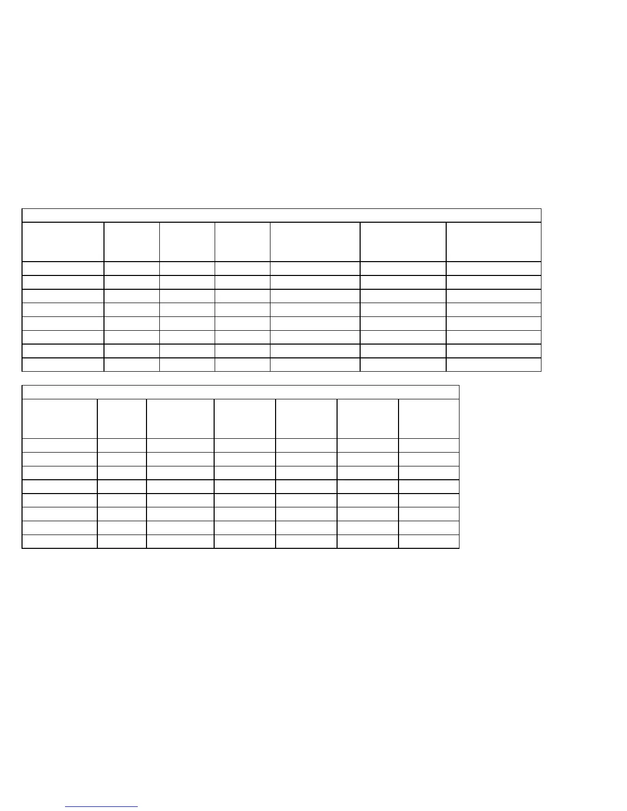
Suggested values for AC Brushless Motors and Drives
SD
Drive
SD3, SD1
750 W
motors
SD3, SD1
1,2 KW
motors
SD3, SD1
(finned heatsink)
1,2 KW motors
SD1 45A
(finned heatsink)
3 KW motors
SD1 45A
(finned heatsink)
4 KW motors
Parameters Axes Values Values Values Values Values
21-24 1-4 0.23 0.5 0.23 0.23 0.23
132-135 5-8 0.23 0.5 0.23 0.23 0.23
25-28 1-4 12.0 9.0 12.0 12.0 14.5
236-239 5-8 12.0 9.0 12.0 12.0 14.5
20 N/A 72 72 72 72 72
29 N/A 150 150 150 150 150
30 N/A 180 180 180 180 180
Suggested values for DC Brush Motors and Drives
Servo
Drive
9A Drive,
16 in/lb
motors
12A Drive,
29 in/lb
motors
15A Drive,
29 in/lb
motors
15A Drive,
40 in/lb
motors
25A Drive,
40 in/lb
motors
Parameters Axes Values Values Values Values Values
21-24 1-4 0.028 0.02 0.027 0.03 0.04
132-135 5-8 0.028 0.02 0.027 0.03 0.04
25-28 1-4 0.68 0.68 0.68 0.68 0.68
236-239 5-8 0.68 0.68 0.68 0.68 0.68
20 N/A 72 72 72 72 72
29 N/A 150 150 150 150 150
30 N/A 180 180 180 180 180
Parameter 31 - Legacy SPIN232 Com Port
For values 1-255, CNC11 will attempt to open that COM port and send out spindle commands. CNC11 should be
restarted after changing this value from 0 (disabled) to a valid value. Note that the baud rate is assumed to be 19200 to
work specifically with a SPIN232.
Parameter 33 - Spindle Motor Gear Ratio
NOTICE
The default value for this parameter is 1 and should not be changed unless you have
consulted your dealer or local Technical representative!!!
Parameter 33 is used for the gear or belt ratio between the spindle motor and the chuck in high gear range. It should be
greater than 1.0 if the motor turns faster than the chuck and less than 1.0 if the chuck turns faster than the motor. Note:
this value applies to high range. The ratio between high range and lower ranges is established by the gear ratio
parameters (65-67).