M-Series Operator’s Manual 4/9/15
Parameter 63 - High Power Idle PID Multiplier
This parameter holds the value of a constant used for motor high power idle detection when an axis is not moving and
no job is running, but there is power going into the motor to maintain its position. The default value is 1.5. This is
intended for early detection of an axis if it’s stopped against some abnormal resistance or not tuned correctly, such that
it will probably overheat later.
Parameter 64 – Fourth/Fifth Axis Pairing
This feature enables the 4
th
and 5
th
axes to be paired together or individually be run in a slaved state with any of the
other axes. This is intended to drive 2 screws on opposite sides of a table (probably a router table or gantry system).
Set this parameter to 0 (default) to indicate that no other axis is paired with the 4
th
or 5
th
axis. In order to pair both the
4
th
and 5
th
axes on the same system add the 4
th
axis value with the 5
th
axis value. Example: 4
th
axis paired with the X-
axis and 5
th
axis paired with the Z-axis a value of 49 would be entered into parameter 64. The axes are slaved upon
power up but it is still possible to move the paired (4
th
or 5
th
) axis independently if the axis is labeled.
* NOTE: You cannot run Autotune on paired axes.
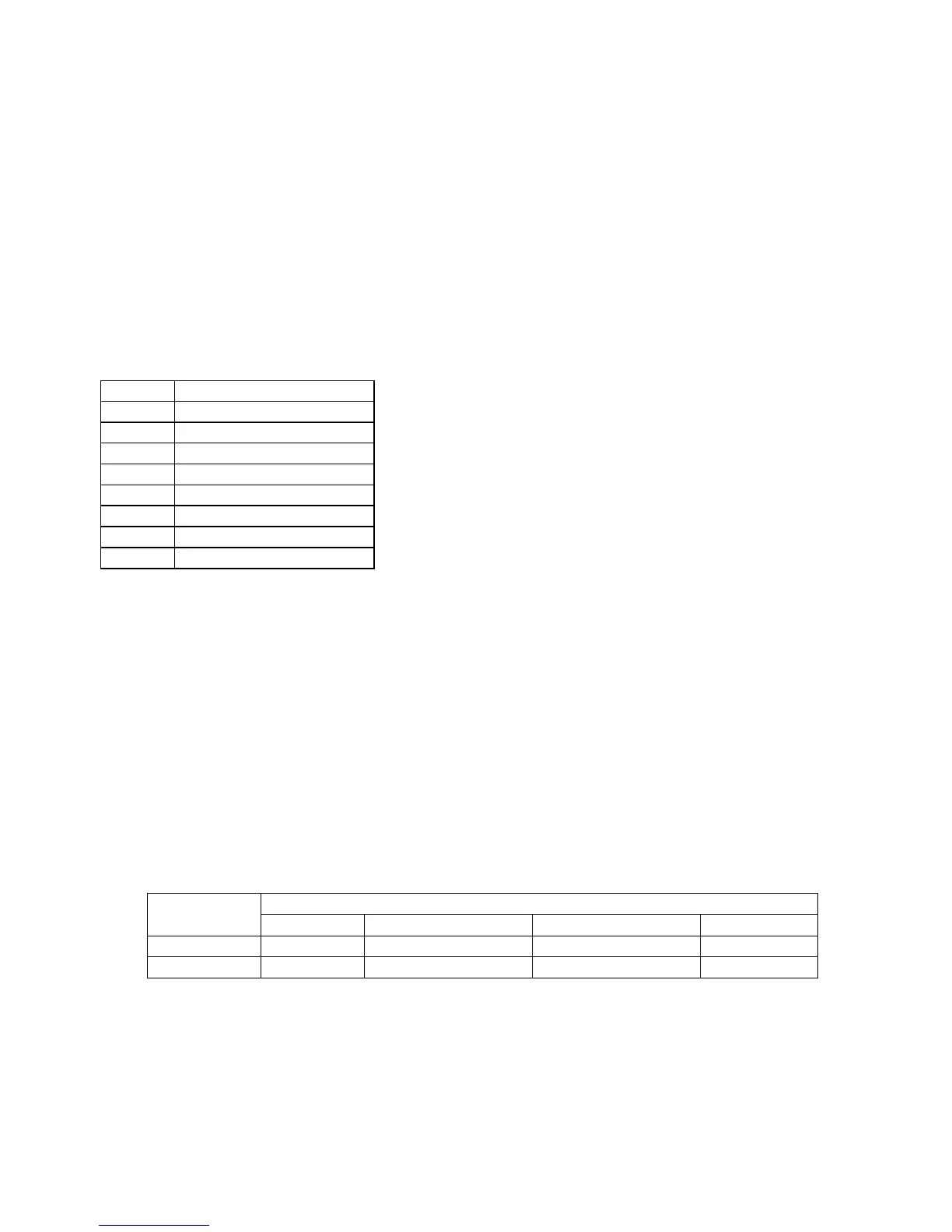
Value Meaning
0 No Pairing (Default)
1 Pair 4
th
axis with 1
st
Axis
2 Pair 4
th
axis with 2
nd
Axis
3 Pair 4
th
axis with 3
rd
Axis
16 Pair 5
th
axis with 1
st
Axis
32 Pair 5
th
axis with 2
nd
Axis
48 Pair 5
th
axis with 3
rd
Axis
64 Pair 5
th
axis with 4
th
Axis
Parameters 65-67 - Spindle Gear Ratios
These parameters tell the control the gear ratios for a multi-range spindle drive. Up to four speed ranges are supported;
high range is the default. Parameters 65-67 specify the gear ratio for each lower range, relative to high range. For
example, if the machine is a mill with a dual range spindle, and the spindle in low range turns 1/10 the speed it turns in
high range, then parameter 65 should be set to 0.1. Note that these values can be signed +/-. So, if switching from
high range to a lower range causes the spindle encoder to count in the opposite direction, then a negative value can be
used to compensate for this behavior.
Parameter 65 is the low range gear ratio.
Parameter 66 is the medium-low range gear ratio.
Parameter 67 is the medium-high range gear ratio.
These parameters work in conjunction with the PLC program, which uses the states of INP63 and INP64 to signal to
the CNC software which range is in effect, according to the table below.
Spindle Range
PLC INPUT
High Range Medium High Range Medium Low Range Low Range
INP63 0 1 1 0
INP64 0 0 1 1
Parameter 68 – Minimum Spindle Speed (Rigid Tapping Parameter)
This parameter holds the value that the spindle slows down to from the programmed spindle speed towards the end of
the tapping cycle. The lower the value, the more accurately the Z-axis will land on target, but at the expense of
possibly stalling the spindle motor which in turn will cause Z-axis to fall short. If this value is too large, the off target
error will increase. The suggested starting value is 640 RPM.