M-Series Operator’s Manual 4/9/15
Parameter 69 – Duration for Minimum Spindle Speed Mode (Rigid Tapping Parameter)
This is the duration of time, in seconds, that the control will stay at minimum spindle speed. If the number is too small,
overshoot will occur. If the number is too large, the user waits longer for the hole to be tapped at the slow speed
specified by parameter 68. The suggested starting value is 1.25 seconds.
Parameter 70 - Offset Library Inc/Decrement Amount
Sets the increment and decrement amount used in the offset library.
Parameter 71 – Part Setup Detector Height
If this Parameter is set to a non-zero value, it indicates that the F3 - Auto feature in part setup should be available
using the tool detector (TT1) instead of the probe. The value in this parameter is the height of the detector. A value of
0 disables this feature.
When this feature is enabled:
a) Probe detection (Parameter 18) is not checked
b) The tool number and/or edge finder diameter entered by the operator are used; Parameter 12 is ignored.
c) The value from Parameter 71 is added to (or subtracted from, depending on approach direction) the part position.
Parameter 72 – Data M Function Options
The setting of this parameter affects the operation of the data M functions M122, M123, and M124.
Bit
Function Description Parameter Value
0 Suppress output of axis labels by M122/M124? Yes = 1, No = 0
1 Insert commas between positions/values with M122/M124? Yes = 2, No = 0
2 Suppress spaces between positions/values outputted by M122/M123/M124? Yes = 4, No = 0
Parameter 73 – Peck Drill Retract Amount (Canned Cycle Parameter)
This specifies the retract amount used during a G73 peck drilling cycle.
Parameter 74 – M-function executed at bottom of tapping cycle (Canned Cycle Parameter)
This specifies the number of the M-function that is executed at the bottom of the G84 tapping cycle (primarily used for
reversing the spindle in preparation for pulling out of the tap hole). This also specifies the number of the M-function
that is executed after the G74 countertapping cycle is done (returned to the initial point).
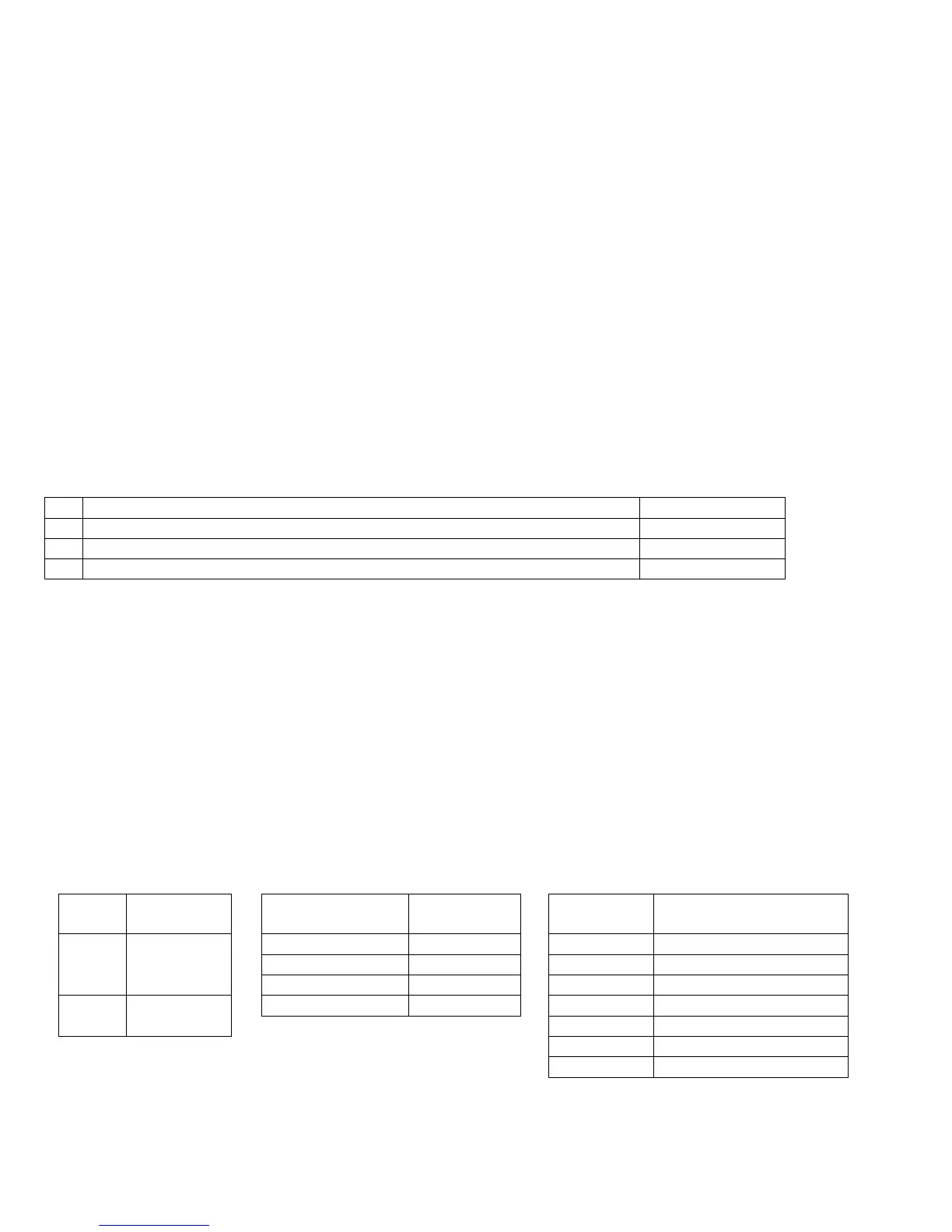
Parameter 75 – Summing Control
This parameter controls the type of position to be summed (local or machine), and which axes are to be summed
together and which axis will bear the effects of the the summing. The parameter can contain up to four digits. The
sign of the parameter value and the position and value of each digit has special significance as indicated in the tables
below:
Sign Position
Type
Parameter Digit
Position
Summed
Axis
Digit Value Meaning
1's Column Axis 1 0 Summing off
10's Column Axis 2 1 through 4 Axis to Sum with
+ Sum
Machine
Coordinates
100's Column Axis 3 5 (Reserved)
1,000's Column Axis 4 6 Disable display - Sum Local
Coordinates
7 Display if moved
8 Display if other moves
9 (Reserved)