M-Series Operator’s Manual 4/9/15
The “Summed Axis” is the axis that bears the position sum of itself with the “Axis to Sum with”. The DRO display
of the “Summed Axis” will show this summed position. The DRO will display both labels when displaying a summed
axis. Furthermore, G-codes that command movement on the “Summed Axis” will have their positions offset by the
position of the “Axis to Sum with”.
NOTICE
It is highly recommended that summing be done with Local Coordinates (using the ‘-’
sign in the parameter value). Summing with Machine Coordinates can cause the effective
software travel limits to move, thus resulting in physical overtravel or severely
handicapping the amount of available travel, due to the fact that software travel limits are
defined in terms of Machine Coordinates. Summing with Local Coordinates avoids this
problem.
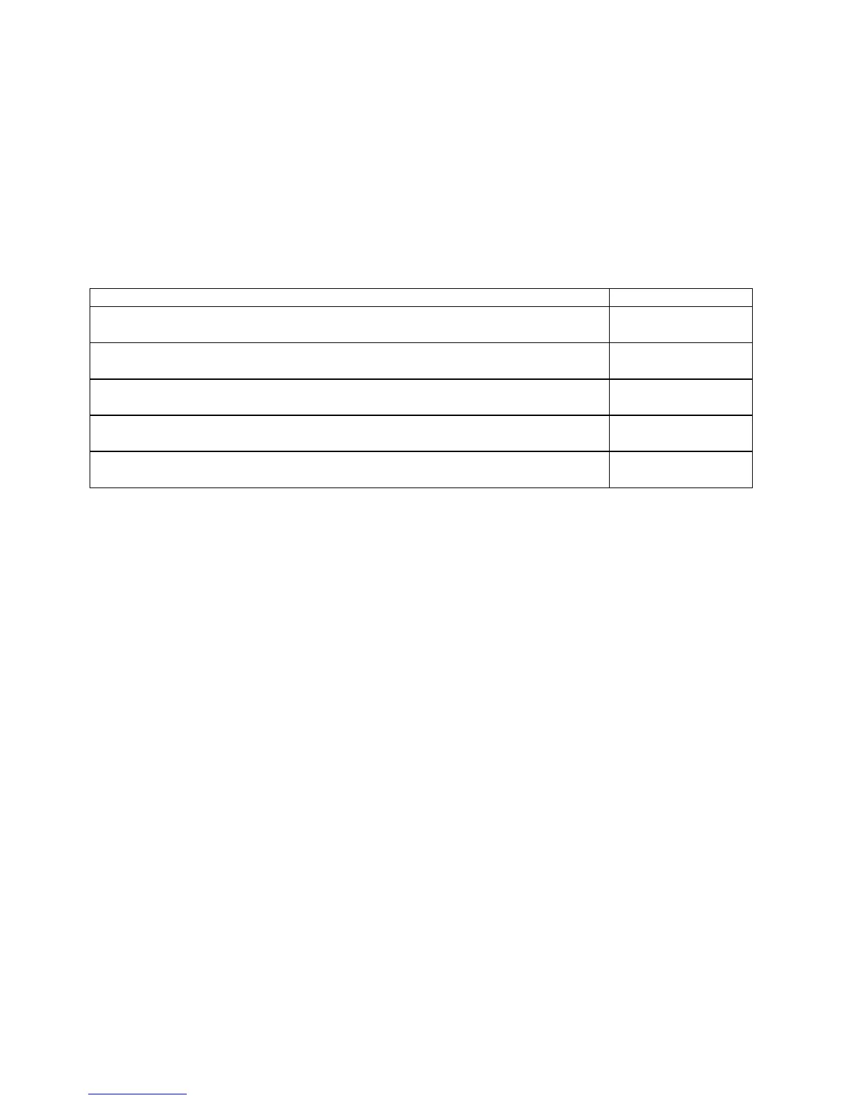
Here are some examples:
Desired Display Parameter
Axis 3 DRO will display the result of axis 3 and 4 machine coordinate positions
summed together.
400
Axis 4 DRO will display the result of axis 4 and 3 local coordinate positions
summed together. Machine coordinate positions are not affected.
-3000
Axis 3 DRO will display the result of axis 3 and 4 local coordinate positions
summed together. Axis 4 DRO display will be disabled.
-6400
Axis 4 DRO will display the result of axis 4 and 3 local coordinate positions
summed together. Axis 3 DRO display will be disabled.
-3600
Axis 3 DRO will display the result of axis 3 and 4 local coordinate positions
summed together. Axis 4 will be displayed only if it moves.
-7400
Parameter 76 – Manual Input Unrestricted Distance
This parameter is intended to be used with Z-axis summing. It defines the maximum distance from the summed axis
start of travel in which manual movements can occur without causing a fault. Use a negative value to specify a
distance from the minus travel limit, a positive value for a distance from the plus travel limit.
When used with manual drilling, for example, setting this parameter will allow the operator to keep a hand on the quill
at all times and even begin pulling on the quill in anticipation of a programmed stop.
Setting this value to zero will cause a fault if there is any manual movement.
To completely disable manual movement restrictions, set this parameter to a value exceeding the total travel of the
summed axis.
Minimum = -99999.9999, maximum = 9999.9999, default = 0, typical = +/- 1.0 inch or +/- 20.0 mm
Parameter 77 – Manual Input Movement Tolerance
This parameter specifies the manual movement tolerance while a job is running. It is intended for use with a quill
locking mechanism. It allows the lock to distort and/or slip a small amount when under stress. If the quill moves more
than the given tolerance, the job will stop with a fault. A typical setting for Parameter 77 is 0.005 inches.
Parameter 78 – Spindle Speed Display and Operations
Bit 0 (value = 1) specifies how the spindle speed is determined and displayed in the CNC software status window.
When turned on (value = 1), the spindle speed is determined by reading the encoder feedback from the axis specified
according to parameter 35. Which has the number of encoder counts/revolution specified in parameter 34. When
turned off (value = 0), the displayed speed is not measured; the speed is calculated based upon the programmed speed,
spindle override adjustment, and gear range.
Bit 1 (value = 2) allows the control to prorate the programmed feedrate to be proportional to the spindle speed if the
spindle speed ever slows down below the spindle speed threshold percent as set by parameter 149.