M-Series Operator’s Manual 4/9/15
Parameters 87-90 (and also 252-255) - Autotune Ka Performance parameters
These parameters are used by autotune. Increasing the value will increase the Ka used by autotune which when used
will increase the PID used during acceleration. The default value is 0. The maximum value is 50 and the minimum
value is 0. Values for axes 1-4 are specified in parameters 87-90. Values for axes 5-8 are specified in parameters 252-
255.
Parameters 91-94 (and also 166-169) – Axis Properties
These parameters may be used to set various axis properties. Properties for axes 1-4 are specified in parameters 91-94.
Properties for axes 5-8 are specified in parameters 166-169.
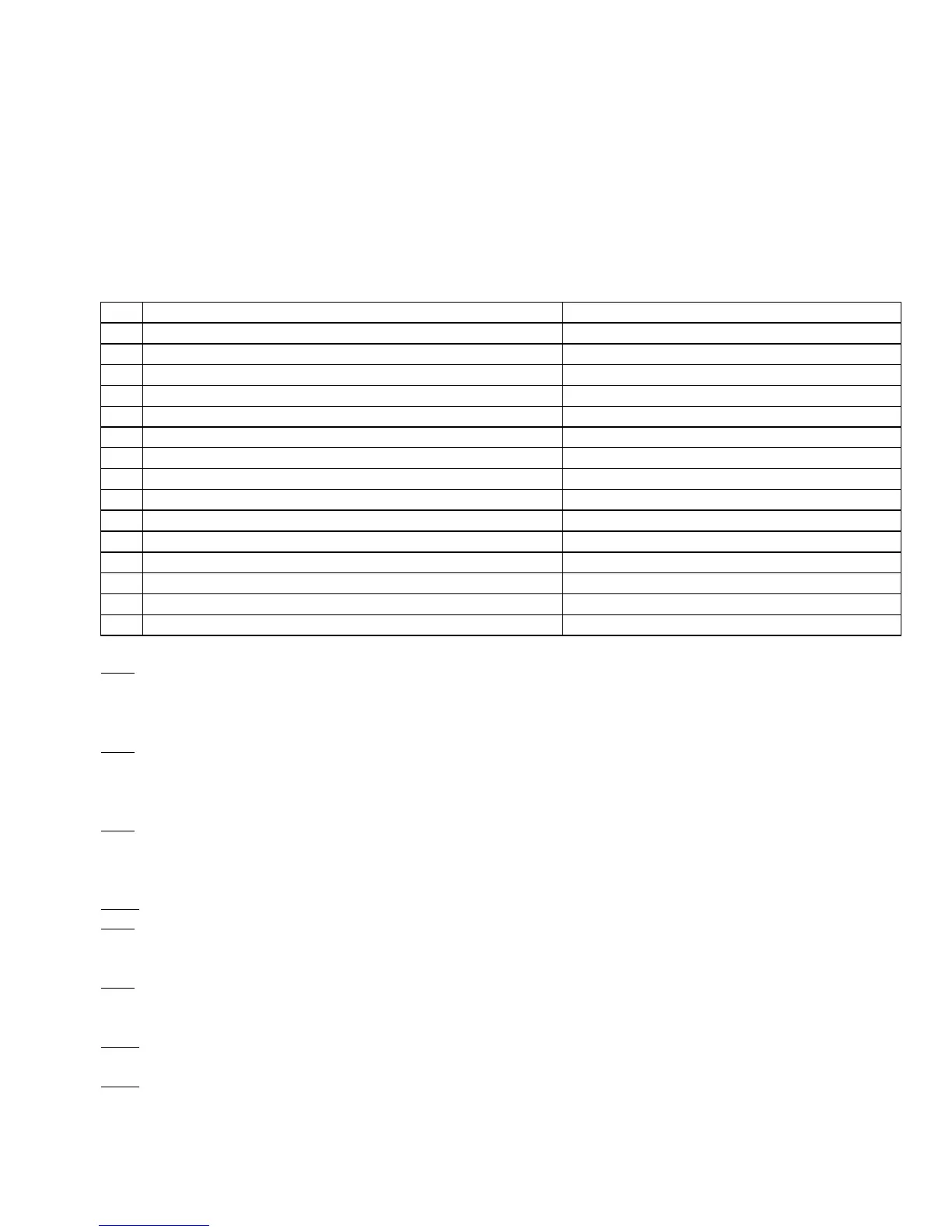
Bit Function Description Parameter Value
0 Rotary/Linear Axis Selection Rotary Axis = 1, Linear Axis = 0
1 Rotary Display Mode Wrap Around = 2, Show Rotations = 0
2 Suppress direction check when doing Tool Check? Don’t Check = 4, Check = 0
3 Suppress park function? Don’t Park = 8, Park = 0
4 NOT USED ON MILL Recommended bit value is 0
5 Linear Display of Rotary Axis Linear Display = 32, Default Rotary = 0
6 4
th
Axis works like Z axis Yes = 64, No = 0
7 NOT USED ON MILL Recommended bit value is 0
8 Axis is triangular rotary? Yes = 256, No = 0
9 Hide axis display from DRO Yes = 512, No = 0
10 Triangular rotary axis type Articulated Head = 1024, Tilt Table = 0
11 Rotation Center is parallel to X? Yes = 2048, No = 0
12 NOT USED Recommended bit value is 0
13 NOT USED Recommended bit value is 0
14 Enable TWCS for Articulated Head machines Yes = 16384, No = 0
Bit 0: Turning this bit on will cause the DRO display for the affected axis to be displayed in degrees. Also this
information is used by Intercon to make rotary axis support available (by setting parameter 94 to 1, indicating that the
fourth axis is rotary). This bit is also used when performing inch/mm conversions: values for a rotary axis will not be
converted since they are assumed to be in degrees regardless of the system of linear units.
Bit 1: This bit has no effect unless Bit 0 (mentioned above) is turned on. When this bit is turned on, a “Wrap Around”
display is shown on the DRO. A “Wrap Around” Rotary Display is a display in degrees without the number of
rotations shown. If this bit is turned off, the number of rotations away from 0 degrees will be shown alongside the
degree display.
Bit 2: This bit will only affect the Z-axis. It controls whether or not a direction check will be performed when the
Tool Check button is pressed. If this bit is turned on, direction checking is turned off, and thus, there is a possibility
for the Z-axis to move downward unexpectedly, depending on the Z value of Return Point #1 (G28). Therefore, it is
best in most cases to leave this bit turned off to allow direction checking to be turned on (value = 0).
Bit 3: Setting this bit prevents <F1> (Park) in the Shutdown menu from parking this axis.
Bit 5: This setting overrides only the DRO display options for an axis that has bit 0 set (including the Rotary Display
Mode – bit 1) so that the display does not reflect a degree symbol or any indication of the number of rotations, but
appears as a linear axis.
Bit 6: This bit only works for Parameter 94 (4
th
axis). Setting this bit will cause the 4
th
axis to respond to Z-axis only
commands just like the Z-axis, for example issuing an M25 with this bit set will cause the Z and 4
th
axes to go the
home (G28) position.
Bit 8: This setting is used in conjunction with bit 10. It only works for parameter 166 (5
th
axis). Setting this bit on will
identify this axis as a Triagular Rotary, which may either be an Articulated Head axis, or a Tilt Table axis.
Bit 9: This setting will hide the affected axis from the DRO display. Note that this does not prevent such an axis from
being commanded to move.