M-Series Operator’s Manual 4/9/15
8-12
Contour Digitize Notes
Contour digitizing creates an M&G code file with a .cam extension. The structure of the .cam file starts with a
header of comments indicating some of the parameters used when digitizing the contour. Next is the contour itself,
which is outputted as a subprogram. The M&G codes are preceded by an O9800 (start of subprogram) and
followed by an M99 (end of subprogram). The end of the .cam file contains the initial positioning moves and a call
to the contour subprogram (G65 P9800).
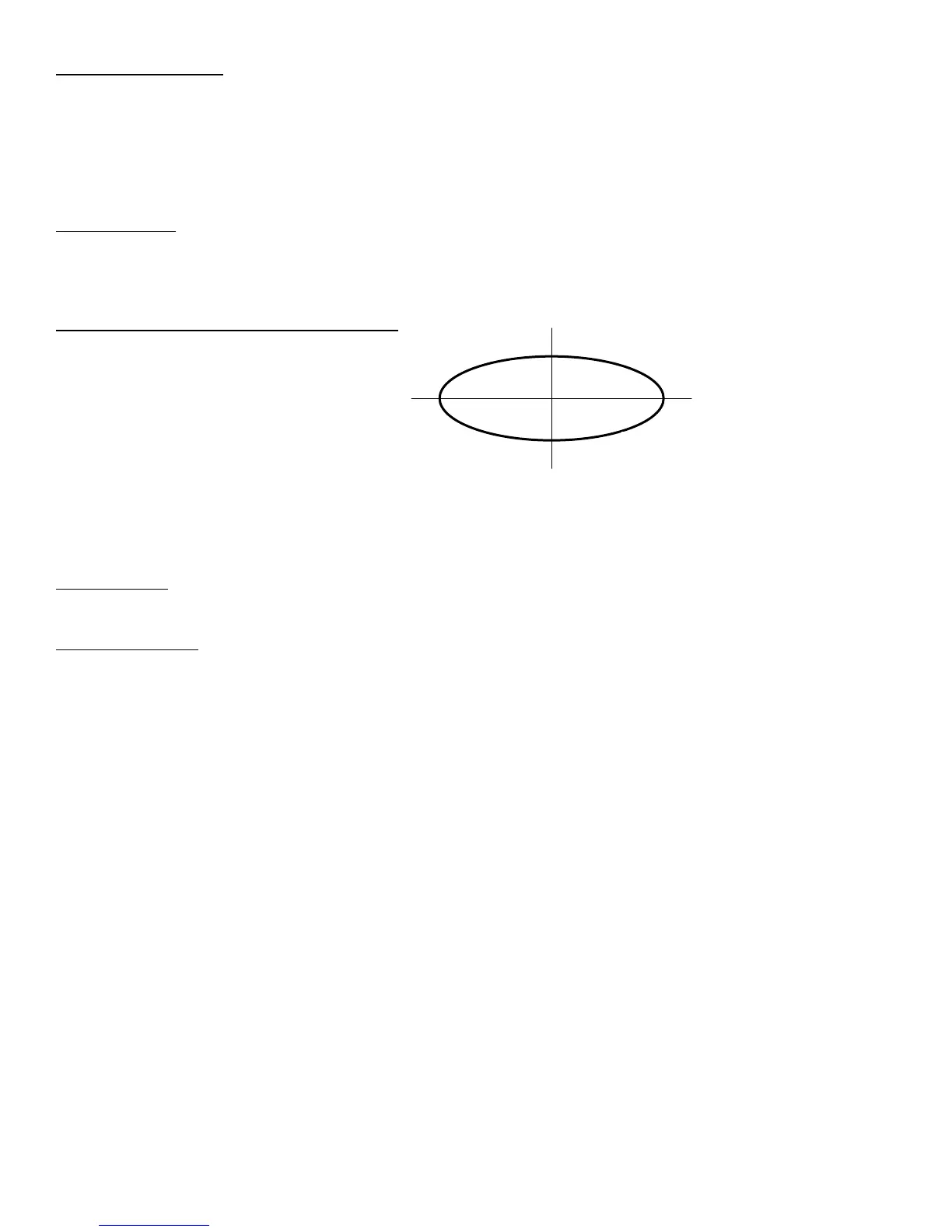
Probing direction: When starting the digitizing cycle, choose a starting point where the X travel will contact a point
on the cam on the Y axis. The probe tip will move toward the center line in the X direction until it contacts the
cam, then will move either clockwise or counterclockwise around the cam, depending on which quadrant you
started the cycle (see Table 1).
Table 1 – Probe direction by starting quadrant
X Y Probe travels
- - CW
- + CCW
+ + CW
+ - CCW
- 0 CW
+ 0 CCW
If the probe bypasses a contact point on the Y axis, it will continue moving in the X direction across the center line
until it reaches the patch length limit and faults out.
Canceling a job: Unlike grid or radial digitizing if you cancel a contour operation before it is completed you will
not be able to restart the contour at the point of interruption to continue the cycle. You will need to start over.
Before running a job: Before running a job created by contour digitizing, you will need to add some information to
the file to define any required tool change, cutter compensation and height offset commands.
1. Do a search in the G code for the phrase “Add Comp Here.”
2. Refer to the descriptions of G40, G41 and G42 in Chapter 12.
3. Add the proper G code to the file after the “Add Comp Here” prompt.
4. Save the file, and run your job.