M-Series Operator’s Manual 4/9/2015 10-5
F9 – Setup
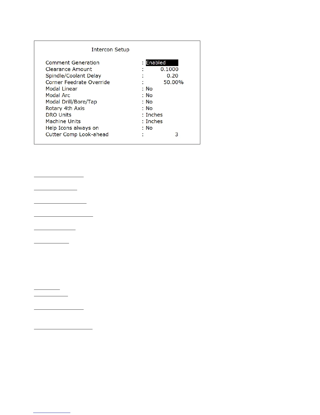
Choosing F9 - Setup will display the Setup menu where certain options can be set. The Setup menu
appears as below.
Use the up and down arrow keys to move. Clearance Amount, Spindle/Coolant Delay, and Corner Feedrate Override
require a value to be typed in. The other fields have fixed values that may be toggled by using the F1 - Toggle key.
Comment Generation: When this field is set to Enabled, Intercon will put a comment describing the operation type
before each block. Disabling Comment Generation will make the CNC files generated by Intercon smaller.
Clearance Amount: This is the distance that Intercon raises the Z-axis above the programmed surface height in
pockets, facing and frame mills when traveling across the work piece.
Spindle/Coolant Delay: Set this delay to the time in seconds you want Intercon to wait for the spindle to get up to
speed and the coolant to begin flowing.
Corner Feedrate Override: This is the percent feedrate that will be used in the corners of rectangular pockets and inside
frame mills. The default value is 50%.
Modal Operations: These options specify whether to automatically insert the same operation after the first has been
accepted. Once modal insert mode has begun, press ESC to insert a different operation.
Rotary 4
th
Axis: This option specifies whether or not 4
th
axis movement fields appear in Linear and Rapid moves and
whether or not the Intercon program will post 4
th
axis movement. This option affects the value in the 4
th
axis
configuration only (parameter 94). Note that although Intercon is restricted to working with 1 rotary axis at a time, it
can be directed to utilize the 5
th
axis as its rotary axis instead of the 4
th
. To make Intercon to utilize the 5
th
axis as its
rotary axis instead of the 4
th
axis, the 4
th
axis configuration (parameter 94) must have its rotary property turned off (bit
0 = 0) and the 5th axis configuration (parameter 166) must have its rotary property turned on (bit 0 = 1). See chapter
14 for details about parameters 94 and 166.
DRO Units: Specifies the Units used for the DRO. It affects the corresponding field in the Control Configuration.
Machine Units: Specifies the Units used for machining. It affects the corresponding field in the Control Configuration
of the CNC software. The posted G-code will contain a G20 for Inches mode and a G21 for Metric mode.
Help Icons always on: Toggle between yes or no. Selecting “yes” means that help information will always be
displayed when editing operations. “No” means that you will have to press a key to get help. Whether set to “yes” or
“no”, the help screens can always be toggled on or off by pressing the F5 - Help key when editing an operation.
Cutter Comp Look-ahead: This sets the number of segments that can be parsed ahead when Cutter Comp is turned on.
F10 – Post
Choosing F10 - Post will post the current program. Posting is the process of converting the operations
into G-codes. When the posting process is completed, Intercon is exited. The Intercon program is also saved as part of
the posting.