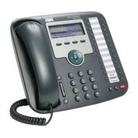
D-2
Cisco Unified IP Phone 7931G Administration Guide for Cisco Unified Communications Manager 8.0 (SCCP and SIP)
OL-20798-01
Appendix D Technical Specifications
Cable Specifications
Cable Specifications
• RJ-9 jack (4-conductor) for handset and headset connection.
• RJ-45 jack for the LAN 10/100BaseT connection (labeled 10/100 SW).
• RJ-45 jack for a second 10/100BaseT compliant connection (labeled 10/100 PC).
• 48-volt power connector.
Network and Access Port Pinouts
Although both the network and access ports are used for network connectivity, they serve different
purposes and have different port pinouts.
Network Port Connector
Table D-2 describes the network port connector pinouts.
In this table, “BI” stands for bidirectional, and DA, DB, DC and DD stand for “Data A”, “Data B”,
“Data C” and “Data D”, respectively.
Access Port Connector
Table D-3 describes the access port connector pinouts.
In this table, “BI” stands for bidirectional, and DA, DB, DC and DD stand for “Data A”, “Data B”,
“Data C” and “Data D”, respectively.
Table D-2 Network Port Connector Pinouts
Pin Number Function
1BI_DA+
2BI_DA-
3BI_DB+
4BI_DC+
5 5BI_DC-
6 6BI_DB-
7 7BI_DD+
8BI_DD-
Table D-3 Access Port Connector Pinouts
Pin Number Function
1BI_DB+
2BI_DB-
3BI_DA+
4 BI_DD+
55BI_DD-
 Loading...