Chapter 5 Clustering Switches
Planning a Switch Cluster
5-6
Catalyst 2900 Series XL and Catalyst 3500 Series XL Software Configuration Guide
78-6511-05
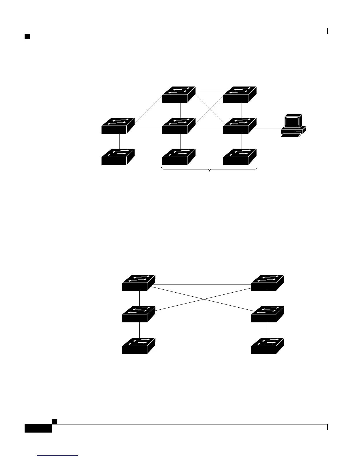
Figure 5-1 A Cluster with a Standby Command Switch
Figure 5-2 shows a network cabled to allow the standby switch to maintain
management contact with the member switches if the cluster command switch
fails. Spanning Tree Protocol (STP) prevents the loops in such a configuration
from reducing performance.
Figure 5-2 Redundant Cabling to Support HSRP
Catalyst 2900 and 3500 XL
member switches
Command switch Standby
command switch
Cluster
Management Suite
1900/2820
member switches
HTTP
33950
Member 4Member 2
172.20.128.221172.20.128.222
Virtual IP: 172.20.128.223
Member 3
Member 1
Standby
command
switch
Active
command
switch
33018
 Loading...


