GR740-UM-DS, Nov 2017, Version 1.7 110 www.cobham.com/gaisler
GR740
10.6.3 Mux configuration register
Table 97. 0x20 - MUXCFG - Mux configuration register
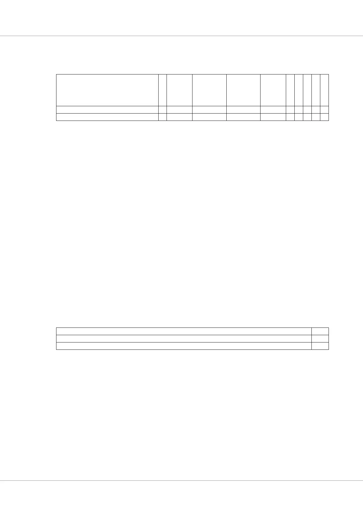
10.6.4 FT diagnostic address register
Table 98. 0x24 - FTDA - FT diagnostic address register
31 20 19 18 16 15 12 11 8 7 5 4 3 2 1 0
ERRLOC D
D
E
R
R
DWIDTH BEID RESERVED DATAMUX C
E
M
B
A
U
P
D
B
A
E
N
C
O
D
E
E
D
E
N
0x000 0 * 0b0001 0 0 0 0 0 0 0
r r r r r rw rwrwrwrwrw
31: 20 Diag data read error location (ERRLOC) - Bit field describing location of corrected errors for last
diagnostic data read. One bit per byte lane in 64+32-bit configuration.
19 Set high if last diagnostic data read contained an uncorrectable error (read-only)
18: 16 Data width (DWIDTH) - 010=32+16, 011=64+32 bits
15: 12 Back-end identifier (BEID) - “0001” - SDRAM
11: 8 RESERVED
7: 5 Data mux control (DATAMUX) - setting this nonzero switchess in the upper checkbit half with
another data lane.
For 64-bit interface
000 = no switching
001 = Data bits 15:0, 010 = Data bits 31:16, 011: Data bits 47:32, 100: Data bits 63:48,
101 = Checkbits 79:64, 110,111 = Undefined
4 Correctable error masking (CEM) - If set to 1, the correctable error signal is masked out.
3 Enable automatic boundary shifting on write (BAUPD)
2 Enable the code boundary (BAEN)
1 Code selection (CODE) - 0=Code A (64+32/32+16/16+8), 1=Code B (64+16/32+8) (FT only)
0 EDAC Enable (EDEN) - Set to 1 to enable EDAC
31 210
FTDA RES
00
rw r
31: 2 Address to memory location for checkbit read/write (FTDA) - 64/32-bit aligned for checkbits/data
1: 0 RESERVED