GR740-UM-DS, Nov 2017, Version 1.7 320 www.cobham.com/gaisler
GR740
22.3.7 Capability register
Table 407.0x1C- CAP - Capability register
22.3.8 Interrupt map registers
Table 408.0x20+4*n- IRQMAPRn - Interrupt map register n, where n = 0 .. 3
22.3.9 Interrupt available register
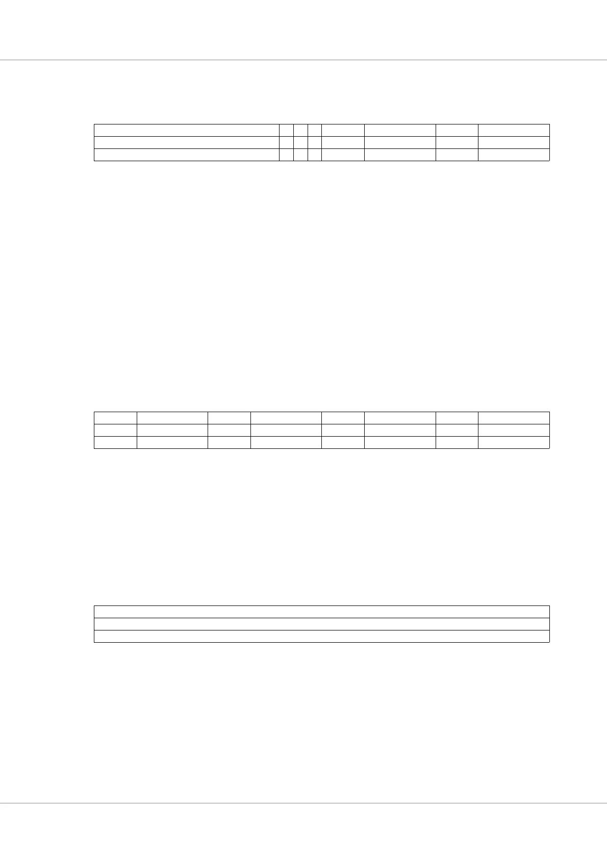
Table 409.0x40 - IAVAIL - Interrupt available register
31 19 18 17 16 15 13 12 8 7 5 4 0
RESERVED PU IER IFL RESERVED IRQGEN RESERVED NLINES
0*0100x40*
r rrrrrrr
31: 19 RESERVED
18 Pulse register implemented (PU) - If this field is ‘1’ then the core implements the Pulse register. Set
to ‘1’ for the first GPIO controller in this implementation.
17 Input Enable register implemented (IER) - If this field is ‘1’ then the core implements the Input
enable register. Set to ‘0’ in this implementation.
16 Interrupt flag register implemented (IFL) - If this field is ‘1’ then the core implements the Interrrupt
available and Interrupt flag registers (registers at offsets 0x40 and 0x44). Set to ‘1’ in this implemen-
tation.
12: 8 Interrupt generation setting (IRQGEN) - Set to 4 to signify that the core has Interrupt map registers
allowing software to dynamically map which lines that should drive interrupt lines 16 to 19..
7: 5 RESERVED
4: 0 Number of pins in GPIO port - 1 (NLINES)
The field has value 15 for the first GPIO port and 21 for the second GPIO port.
31 29 28 24 23 21 20 16 15 13 12 8 7 6 4 0
RESERVED IRQMAP[i] RESERVED IRQMAP[i+1] RESERVED IRQMAP[i+2] RESERVED IRQMAP[i+3]
0 4*n+i 0 4*n+i+1 0 4*n+i+2 0 4*n+i+3
rrwrrwrrwrrw
31: 0 IRQMAP[i] : The field IRQMAP[i] determines to which interrupt I/O line i is connected. If IRQ-
MAP[i] is set to x, IO[i] will drive interrupt 16+x. Several I/O can be mapped to the same interrupt.
An I/O line’s interrupt generation must be enabled in the Interrupt mask register in order for the I/O
line to drive the interrupt specified by the IRQMAP field.
31 0
IMASK
0xFFFF
r
31: 0 Interrupt available bit field (IMASK) - If IMASK[n] is 1 then GPIO line n can generate interrupts.
This field is read-only has has value 0xFFFF for both GPIO ports. This means that lines 15:0 can be
used for interrupt generation.