GR740-UM-DS, Nov 2017, Version 1.7 451 www.cobham.com/gaisler
GR740
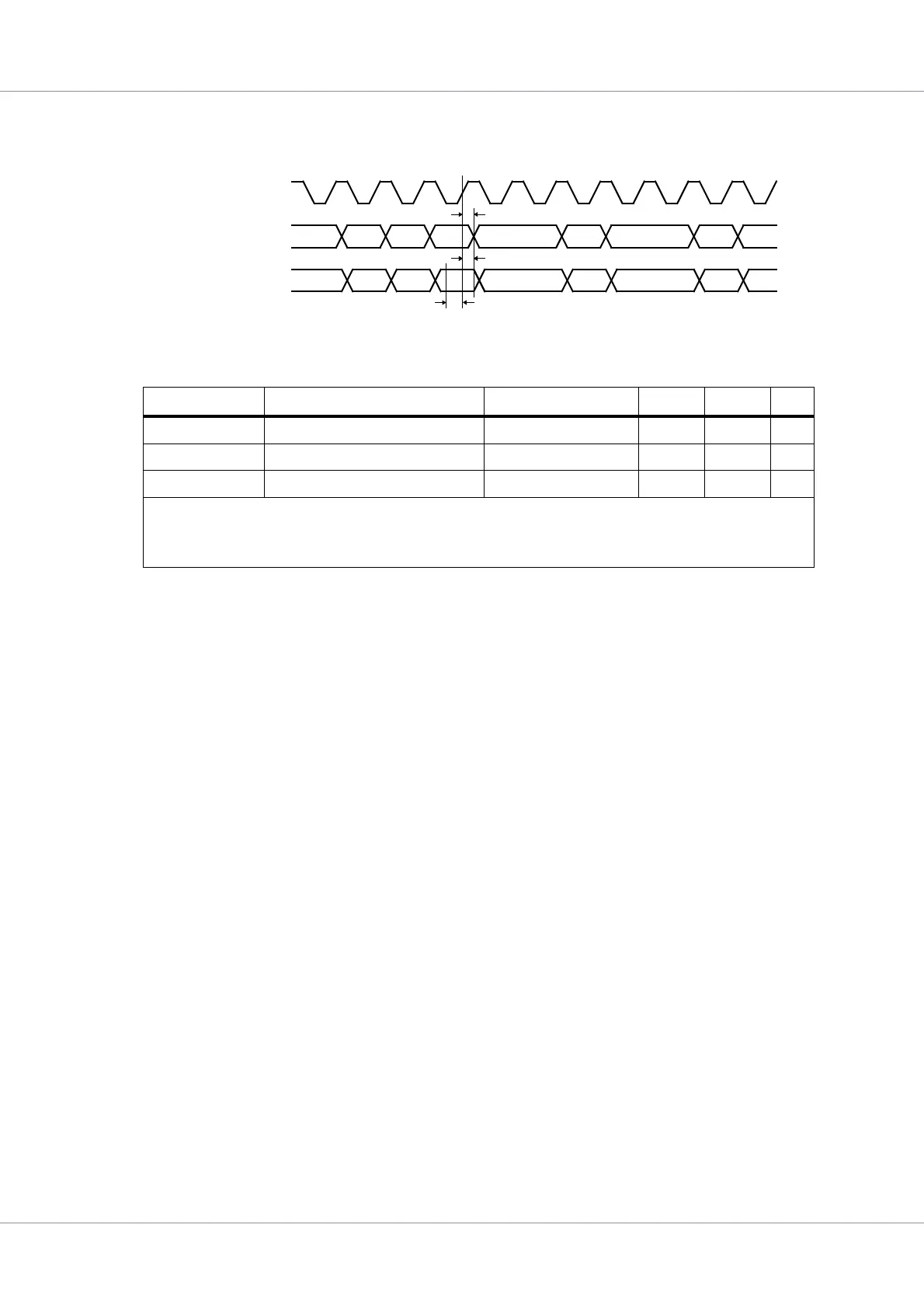
39.5.13 MIL-STD-1553B / AS15531 interface timing
The timing waveforms and timing parameters are shown in figure 66 and are defined in table 590.
Table 590.Timing parameters
Name Parameter Reference edge Min Max Unit
t
1553BRM0
clock to data output delay rising gr1553_clk edge
0
1)
40
2)
ns
t
1553BRM1
data input to clock setup rising gr1553_clk edge
-
3)
-
3)
ns
t
1553BRM2
data input from clock hold rising gr1553_clk edge
-
3)
-
3)
ns
1) Guaranteed by design, not tested
2) Guaranteed by static timing analysis, not tested
3) The inputs are asynchronous to the clock and are internally resynchronized to gr1553_clk
Figure 66. Timing waveforms
t
1553BRM0
outputs
gr1553_clk
inputs
t
1553BRM2
t
1553BRM1
 Loading...