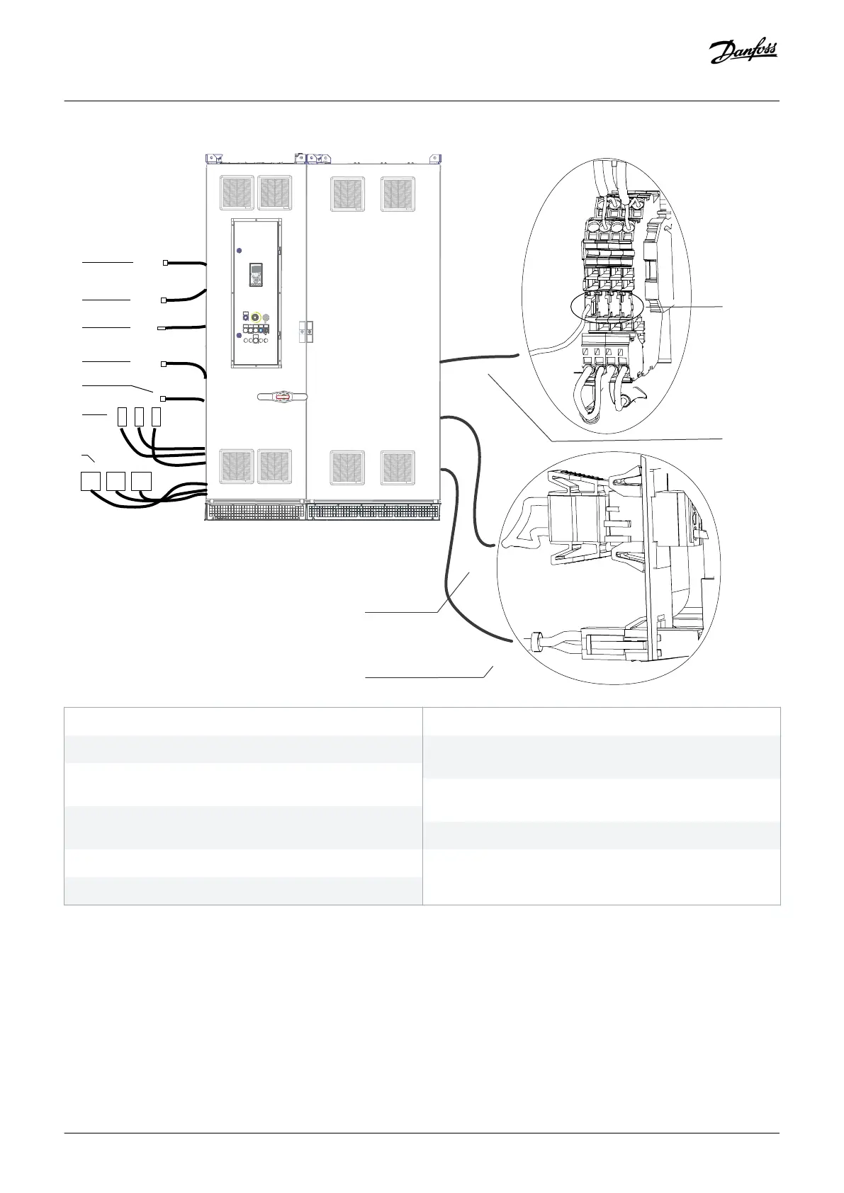
1 Cabinet heater supply harness to input filter cabinet
3 Thermal protection wiring harness in the input filter cabinet
5 PHF contactor 2 supply harness to PHF cabinet (only with
PHF option)
7 Mains cables (L1R/L2S/L3T) to output terminals (L1R/L2S/L3T)
in the input filter cabinet
9 Cabinet heater supply harness to output filter cabinet
11 Thermal protection wiring harness to output filter cabinet
2 DC-link harness to fan supply to input filter cabinet
4 PHF contactor 1 supply harness to PHF cabinet (only with
PHF option)
6 Mains cables R, S, T to input terminals (R/S/T) in the input
filter cabinet
8 DC-link harness to fan supply in output filter cabinet
10 Available terminal connections
Illustration 39: Split Shipment Electrical Connections (Input Power Options Cabinet + E6h Drive Cabinet)
Electrical Installation
Operating Guide | VLT® AQUA Drive FC 202
AQ262141056213en-000101 / 130R0882 | 65
Danfoss A/S © 2018.10

 Loading...


