5.7.6.8 Insulation Monitor
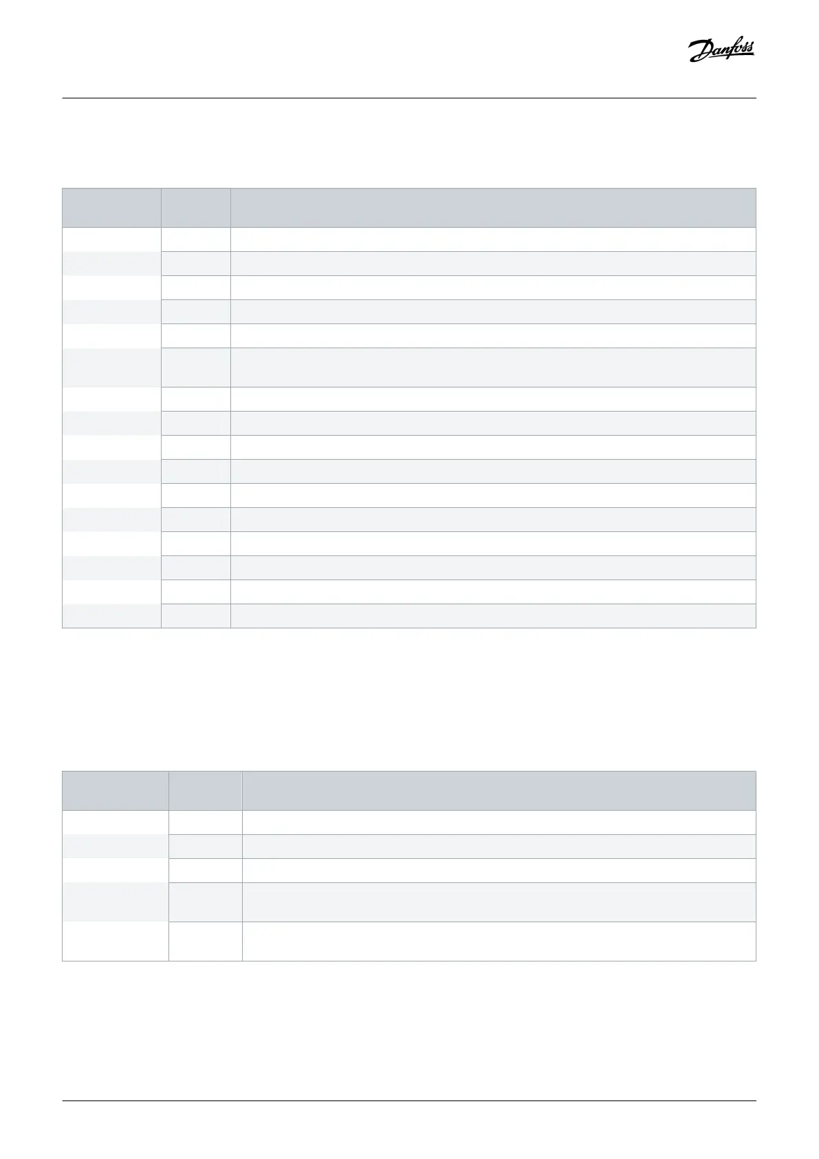
Table 40: Auxiliary Function Option Codes
Character posi-
tion
Option
code
Description
23–24 A5 Insulation monitor
AD AC socket+cabinet light + insulation monitor
AG AC socket+cabinet light + extended I/O terminals + insulation monitor
AI AC socket+cabinet light + extended I/O terminals + cabinet heater + insulation monitor
AJ AC socket+cabinet light + extended I/O terminals + motor heater control + insulation monitor
AK AC socket+cabinet light + extended I/O terminals + cabinet heater + motor heater control + insula-
tion monitor
AM AC socket+cabinet light + cabinet heater + insulation monitor
AN AC socket+cabinet light + cabinet heater + motor heater control + insulation monitor
AO AC socket+cabinet light + motor heater control + insulation monitor
AR Extended I/O terminals + insulation monitor
AT Extended I/O terminals + cabinet heater + insulation monitor
AU Extended I/O terminals + cabinet heater + motor heater control + insulation monitor
AV Extended I/O terminals + motor heater control + insulation monitor
AX Cabinet heater + insulation monitor
AY Cabinet heater + motor heater control + insulation monitor
AZ Motor heater control + insulation monitor
The insulation monitor option monitors the supply and insulation faults within the insulation level in an IT supply network with an
insulation monitor in the control compartment.
5.7.6.9 Indicator Lights and Reset Buttons
Table 41: Door-mounted Option Codes
Character posi-
tion
Option
code
Description
28–29 D1 Indicator lights and reset button
DA Indicator lights and reset button + emergency switch off and emergency push-button
DB Indicator lights and reset button + STO w/ emergency push-button (no functional safety)
DC Indicator lights and reset button + STO/SS1 w/ emergency push-button + safely limited speed
(TTL encoder)
DE Indicator lights and reset button + STO/SS1 w/ emergency push-button + safely limited speed
(HTL encoder)
The indicator light and reset button option includes indicator lights on the control compartment door for run and fault states of the AC
drive. The door also has a button for the reset function of the drive.
Electrical Installation
Operating Guide | VLT® AQUA Drive FC 202
AQ262141056213en-000101 / 130R0882
78 | Danfoss A/S © 2018.10

 Loading...


