8.2.1 CONTROL
NOTE: Step 1 is only applicable to DSE8x10 controllers.
CAUTION!: Failure to perform the Control steps results in poor control over the engine
and alternator. This causes long and unstable synchronising as well as unstable kW and kvar
load sharing.
NOTE: For further details of module configuration, refer to DSE Publication: 057-238
DSE8610 MKII Configuration Suite PC Software Manual.
8.2.1.1 DETERMINING CONNECTIONS AND SETTINGS FOR GOVERNORS
Setting up the Governor (Adjustment of SW1 and SW2)
Before You Start
1. Ensure that the generator is connected to a DEAD BUS BAR WITH NO LOADS connected.
2. With the generator breaker open, set the generator to run at the Nominal Frequency without the
DSE module connected to the Governor. To achieve this you will have to adjust the settings on
the governor.
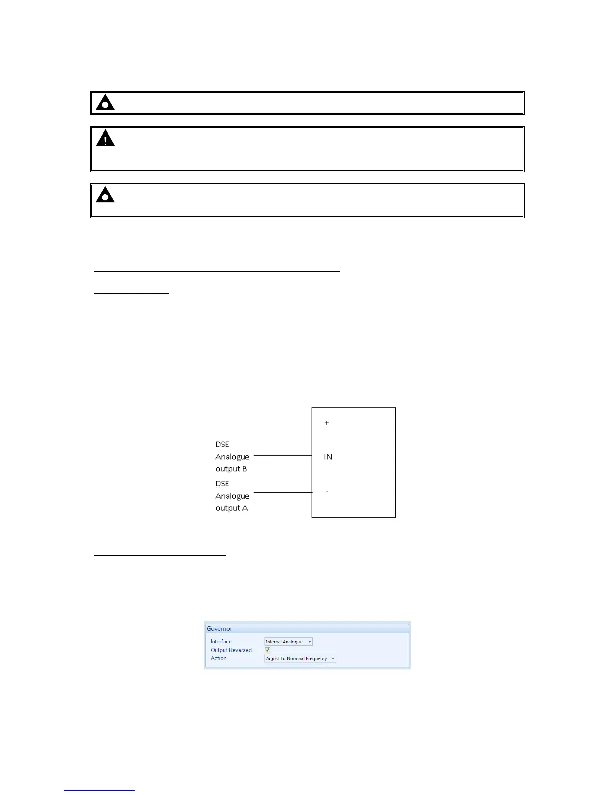
3. Connect the DSE module to the Governor once completed. The DSE controller connects only to
the “-” and “IN” terminals and provides the varying DC voltage to simulate the turning of a
potentiometer. The Analogue output terminals of the DSE controller are connected as follows.
Note that the “+” terminal of the governor is left unconnected
.
Adjustment of Governor SW1
4. Start the generator and ensure that the breaker is left open.
5. Check the direction of drive by increasing and decreasing SW1. If the frequency increases whilst
SW1 is being decreased tick the option ‘Output Reversed’. If moving SW1 does not change the
frequency, check the wiring to the governor for faults.

 Loading...
