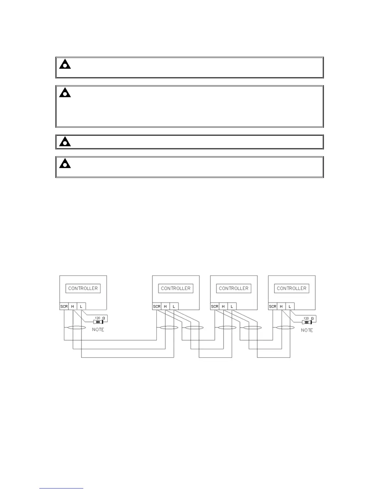
3.6 TYPICAL ARRANGEMENT OF MSC LINK
NOTE: For further details of module configuration, refer to DSE Publication: 057-257
DSE8660 MKII Configuration Suite PC Software Manual.
NOTE: Screened 120 Ω
ΩΩ
Ω impedance cable specified for use with CAN must be used for the
DSENet
®
(RS485) connection.
DSE stock and supply Belden cable 9841 which is a high quality 120Ω
ΩΩ
Ω impedance cable
suitable for DSENet
®
use (DSE part number 016-030)
NOTE: A termination resistor MUST be fitted to the first and last unit on the MSC link.
NOTE: If any number of DSE8x60 are on the MSC link, a maximum of 2x DSE8x80 can be
used. For each DSE8x80 used, the number of available DSE8x60s to be used reduces.
Total of 40 DSE modules can be connected to the MSC link made up of DSE8x10 (up to 32),
DSE8x60 (up to 16) and DSE8x80 (up to 16)
This gives the possibility of:
• 32 generators (DSE8x10) and 8 synchronising transfers (DSE8x60)
• 32 generators (DSE8x10) and 8 generator bus couplers (DSE8x80)
• 24 generators (DSE8x10) and 16 synchronising transfers (DSE8x60)
• 24 generators (DSE8x10) and 16 generator bus couplers (DSE8x80)
• 32 generators (DSE8x10), 14 synchronising transfers (DSE8x60) and
2 generator bus couplers (DSE8x80)

 Loading...
