8.2.1.2 DETERMINING CONNECTIONS AND SETTINGS FOR AVRS
NOTE: Determining the settings of SW1 and SW2 for the AVR MUST only be done once
the setup for SW1 and SW2 for the governor has been complete. Changing engine speed
affects the level of voltage produced.
Setting up the AVR (Adjustment of SW1 and SW2)
Before You Start
1. Ensure that the generator is connected to a DEAD BUS BAR WITH NO LOADS connected.
2. With the generator breaker open, set the generator to run at the Nominal Voltage without the
DSE module connected to the AVR. To achieve this you will have to adjust the settings on the
AVR.
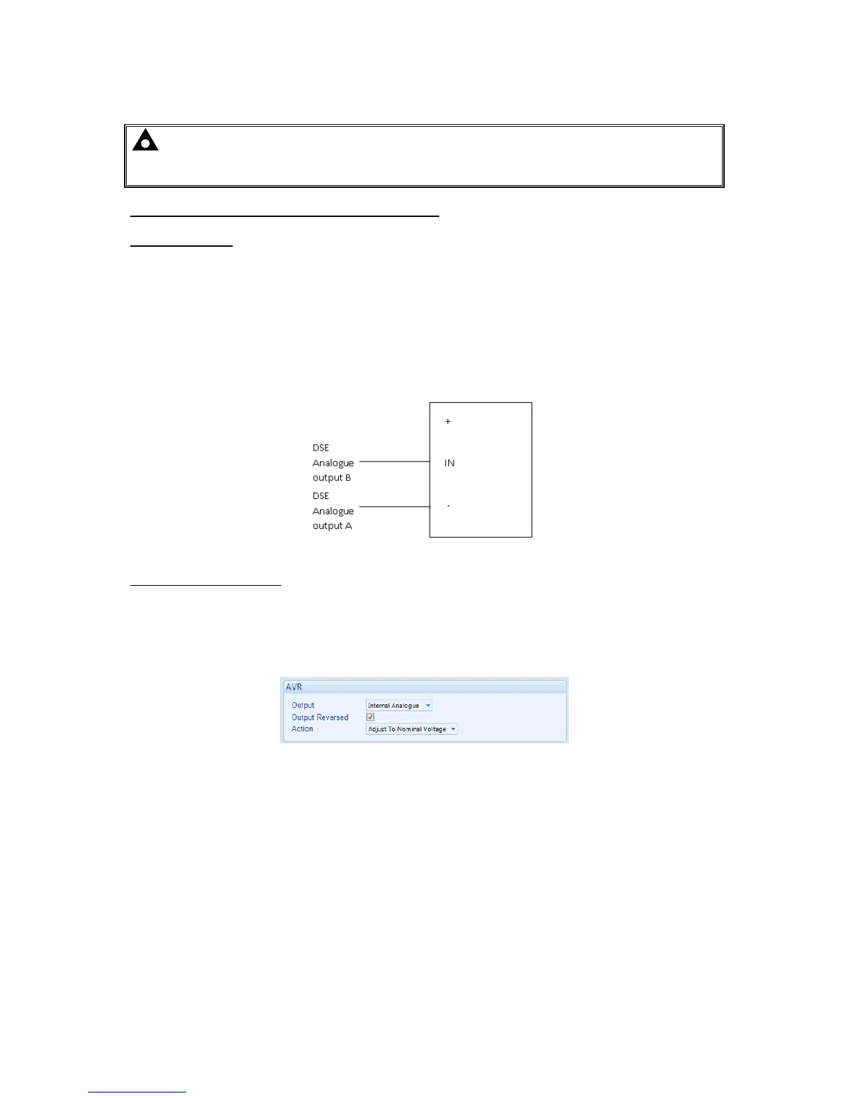
3. Connect the DSE module to the AVR once completed. The DSE controller connects only to the “-
” and “IN” terminals and provides the varying DC voltage to simulate the turning of a
potentiometer. The Analogue output terminals of the DSE controller are connected as follows.
Note that the “+” terminal of the AVR is left unconnected
.
Adjustment of AVR SW1
4. Start the generator and ensure that the breaker is left open.
5. Check the direction of drive by increasing and decreasing SW1. If the voltage increases whilst
SW1 is being decreased tick the option ‘Output Reversed’. If moving SW1 does not change the
voltage, check the wiring to the AVR for faults.
6. Adjust the SW1 setting for the AVR until the generator runs at Nominal Voltage (230V for
example).
7. Stop the generator. SW1 is now complete and needs to be left alone.

 Loading...
