3.2 CONNECTION DESCRIPTIONS
3.2.1 DC SUPPLY & DC OUTPUTS
NOTE: When the module is configured for operation with an electronic engine, Fuel and
Start output requirements may be different. For further details on connection to electronic
engines, refer to DSE Publication: 057-004 Electronic Engines And DSE Wiring
NOTE: For further details of module configuration, refer to DSE Publication: 057-257
DSE8660 MKII Configuration Suite PC Software Manual.
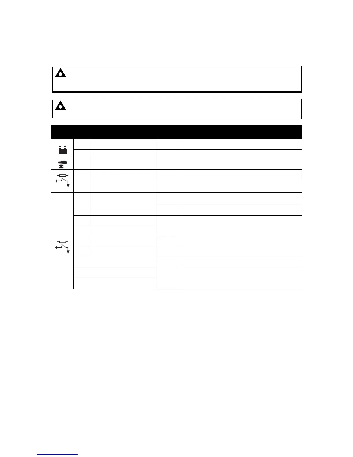
Pin
No
Description
Cable
Size
Notes
1
DC Plant Supply Input
(Negative)
2.5 mm²
AWG 13
Connect to ground where applicable.
2
DC Plant Supply Input
(Positive)
2.5 mm²
AWG 13
Supplies the module and DC Outputs E, F, G, H, I & J
W/L
6 Not Connected
7 DC Output E
1.0 mm²
AWG 18
Plant Supply Positive from terminal 2. 2 A DC rated.
8 DC Output F
1.0 mm²
AWG 18
Plant Supply Positive from terminal 2. 2 A DC rated.
9 DC Output G
1.0 mm²
AWG 18
Plant Supply Positive from terminal 2. 2 A DC rated.
10 DC Output H
1.0 mm²
AWG 18
Plant Supply Positive from terminal 2. 2 A DC rated.
11 DC Output I
1.0 mm²
AWG 18
Plant Supply Positive from terminal 2. 2 A DC rated.
12 DC Output J
1.0 mm²
AWG 18
Plant Supply Positive from terminal 2. 2 A DC rated.
13 Not Connected
14 Not Connected

 Loading...
