8.2.3 COMMUNICATIONS
CAUTION!: Failure to perform the Communications steps results in the controllers being
unable to communicate to the other DSE controllers leading to problems during load sharing.
NOTE: For further details of module configuration, refer to DSE Publication: 057-238
DSE8610 MKII Configuration Suite PC Software Manual.
Check to ensure that all the modules are connected on the MSC link and are communicating
correctly.
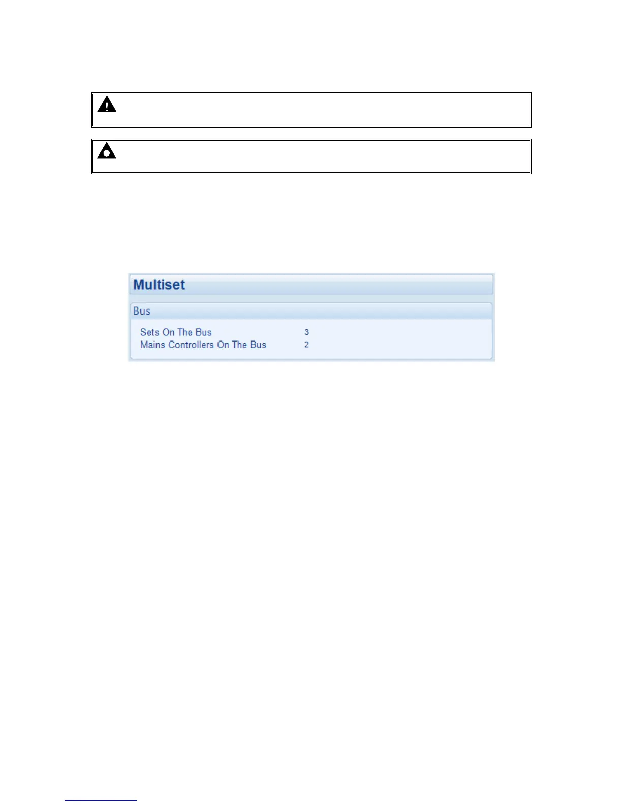
This is tested by connecting the DSE module to a PC with the DSE Configuration Suite PC Software
installed and going to the SCADA | Generator | Multi-Set section. The number of Sets On The Bus
must be the same as the number of DSE8x10s on the MSC link. The number of Mains Controllers ON
The Bus must be the same as the combined number of DSE8x60s and DSE8x80s on the MSC link.
If these numbers do not match up there is a fault on the MSC link. To find the module with the fault,
connect into each module individually until the Sets On The Bus or Mains Controllers ON The Bus
reports 1.
If these numbers do match up the MSC link is working correctly. A further test to perform is to ensure
that the module detects when the MSC link fails. This is tested by removing the MSC link connection
from any module on the MSC link. The numbers shown in SCADA | Generator | Multi-Set change to
reflect the failure and an MSC Failure alarm appears on the module’s display.

 Loading...
