3.2.2 MSC & DSENET
®
NOTE: For further details of module configuration, refer to DSE Publication: 057-257
DSE8660 MKII Configuration Suite PC Software Manual.
NOTE: Screened 120 Ω
ΩΩ
Ω impedance cable specified for use with CAN must be used for the
MSC link.
DSE stock and supply Belden cable 9841 which is a high quality 120 Ω
ΩΩ
Ω impedance cable
suitable for CAN use (DSE part number 016-030)
NOTE: As a termination resistor is internally fitted to the controller, the controller must be
the ‘first’ unit on the DSENet
®
link. A termination resistor MUST be fitted to the ‘last’ unit on
the DSENet
®
link. For connection details, refer to section entitled Typical Wiring Diagram
elsewhere in this document.
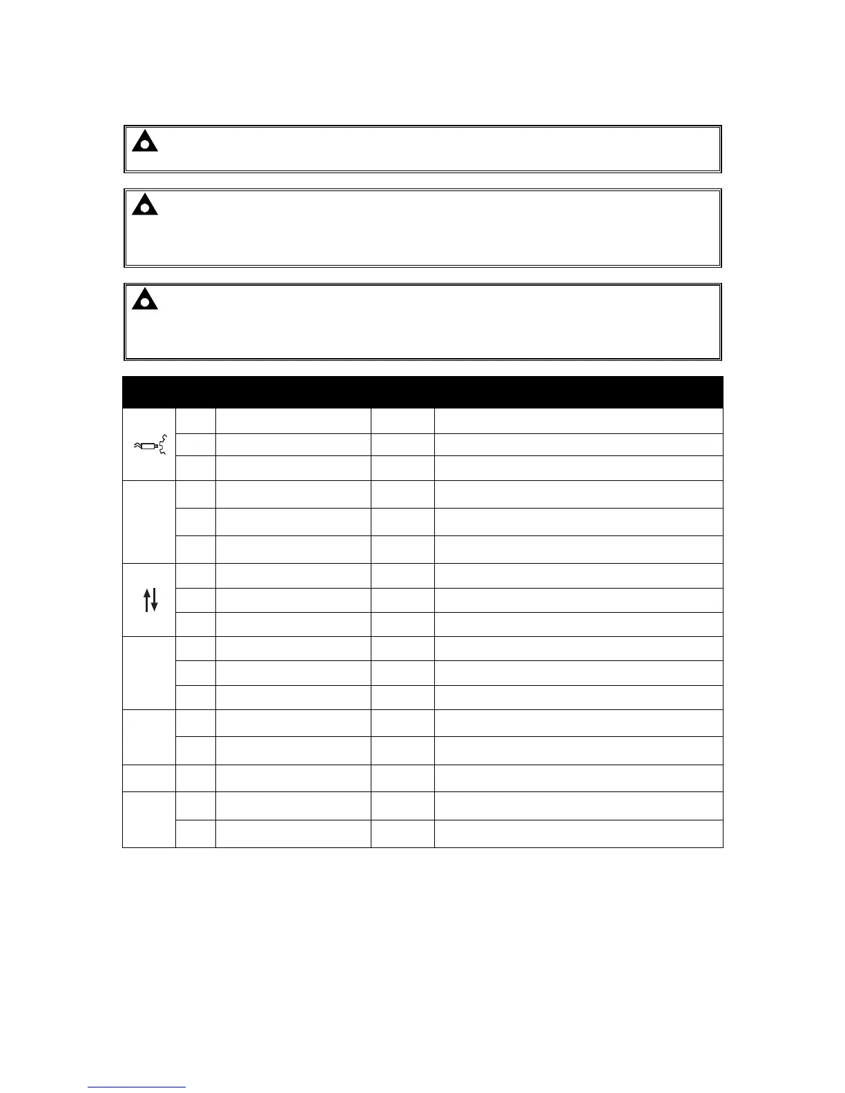
Pin
No
Description
Cable
Size
Notes
23 Not Connected
24 Not Connected
25 Not Connected
ECU
26 Not Connected
27 Not Connected
28 Not Connected
29
DSENet
®
Expansion B
0.5 mm²
AWG 20
Use only 120 Ω CAN or RS485 approved cable
30
DSENet
®
Expansion A
0.5 mm²
AWG 20
Use only 120 Ω CAN or RS485 approved cable
31
DSENet
®
Expansion Screen
Shield
Use only 120 Ω CAN or RS485 approved cable
MSC
32 MSC Port H
0.5 mm²
AWG 20
Use only 120 Ω CAN or RS485 approved cable
33 MSC Port L
0.5 mm²
AWG 20
Use only 120 Ω CAN or RS485 approved cable
34 MSC Port Screen Shield
Use only 120 Ω CAN or RS485 approved cable

 Loading...
