3.2.8 RS485
NOTE: For further details of module configuration, refer to DSE Publication: 057-257
DSE8660 MKII Configuration Suite PC Software Manual.
NOTE: A 120 Ω termination resistor must be fitted across terminals A and B if the DSE
module is the first or last device on the R485 link.
NOTE: Screened 120 Ω
ΩΩ
Ω impedance cable specified for use with RS485 must be used for
the RS485 link.
DSE stock and supply Belden cable 9841 which is a high quality 120 Ω
ΩΩ
Ω impedance cable
suitable for CAN use (DSE part number 016-030)
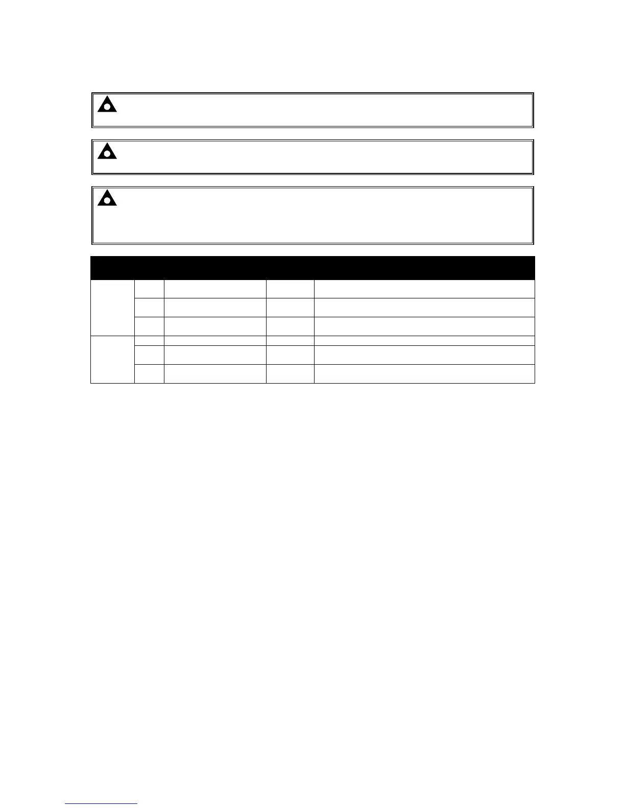
Pin
No
Description
Cable
Size
Notes
RS485
1
71 RS485 Port Screen Shield
Use only 120 Ω CAN or RS485 approved cable
72 RS485 Port B (+)
0.5 mm²
AWG 20
Connect to RXD+ and TXD+
Use only 120 Ω CAN or RS485 approved cable
73 RS485 Port A (-)
0.5 mm²
AWG 20
Connect to RXD- and TXD-
Use only 120 Ω CAN or RS485 approved cable
RS485
2
74 RS485 Port Screen Shield Use only 120 Ω CAN or RS485 approved cable
75 RS485 Port B (+)
0.5 mm²
AWG 20
Connect to RXD+ and TXD+
Use only 120 Ω CAN or RS485 approved cable
76 RS485 Port A (-)
0.5 mm²
AWG 20
Connect to RXD- and TXD-
Use only 120 Ω CAN or RS485 approved cable

 Loading...
