Revision 2016/03, 6ELE, V1.14
4-85
10.04
Derivative Control (D) Unit: 0.01
Settings 0.00 to 1.00 sec Factory Setting: 0.00
This parameter specifies derivative control (rate of change of the input) and associated gain (D). With this
parameter set to 1, the PID output is equal to differential time x (present deviation − previous deviation). It
increases the response speed but it may cause over-compensation.
The parameter can be set during operation for easy tuning.
10.05
Upper Bound for Integral Control Unit: 1
Settings
0 to 100 %
Factory Setting: 100
This parameter defines an upper bound or limit for the integral gain (I) and therefore limits the Master
Frequency.
The formula is: Integral upper bound = Maximum Output Frequency (Pr.01.00) x (Pr.10.05). This parameter
can limit the Maximum Output Frequency.
10.06
Primary Delay Filter Time
Unit: 0.1
Settings 0.0 to 2.5 sec Factory Setting: 0.0
To avoid amplification of measurement noise in the controller output, a derivative digital filter is inserted.
This filter helps to dampen oscillations.
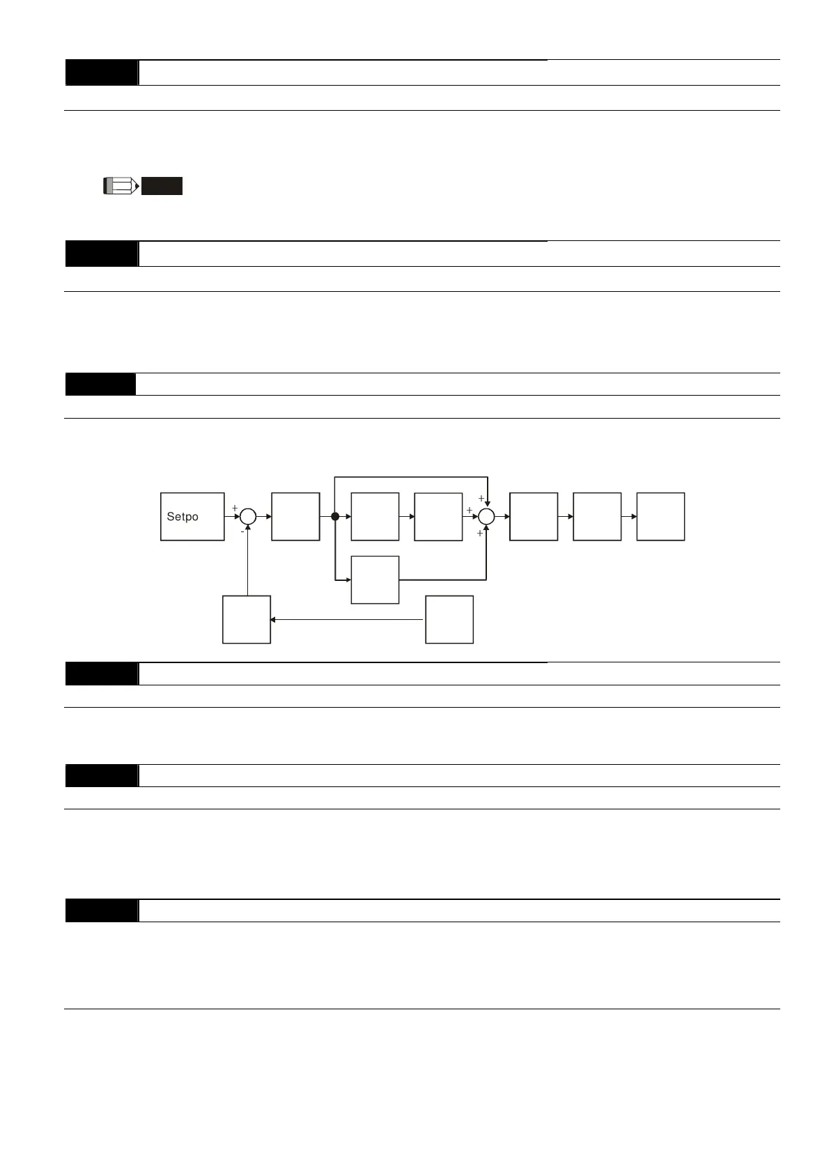
The complete PID diagram is in the following:
P
10.02
I
10.03
D
10.04
10.10
+
-
+
+
+
Setpoint
Input Freq.
Gain
PID
feedback
Integral
gain
limit
Output
Freq.
Limit
Digital
filter
Freq.
Command
10.07
PID Output Frequency Limit
Unit: 1
Settings 0 to 110 % Factory Setting: 100
This parameter defines the percentage of output frequency limit during the PID control. The formula is
Output Frequency Limit = Maximum Output Frequency (Pr.01.00) X Pr.10.07 %. This parameter will limit the
Maximum Output Frequency. An overall limit for the output frequency can be set in Pr.01.07.
10.08
PID Feedback Signal Detection Time Unit: 0.1
Settings 0.0 to d 3600 sec Factory Setting: 60.0
This function in only for ACI signal.
This parameter defines the time during which the PID feedback must be abnormal before a warning (see
Pr.10.09) is given. It also can be modified according to the system feedback signal time.
If this parameter is set to 0.0, the system would not detect any abnormality signal.
10.09
Treatment of the Erroneous Feedback Signals (for PID feedback error)
Factory Setting: 0
Settings 0 Warning and RAMP to stop
1 Warning and COAST to stop
2 Warning and keep operating
This function in only for ACI signal.
AC motor drive action when the feedback signals (analog PID feedback) are abnormal according to
Pr.10.16.
 Loading...