Revision 2016/03, 6ELE, V1.14
2-9
2.4 Control Terminals
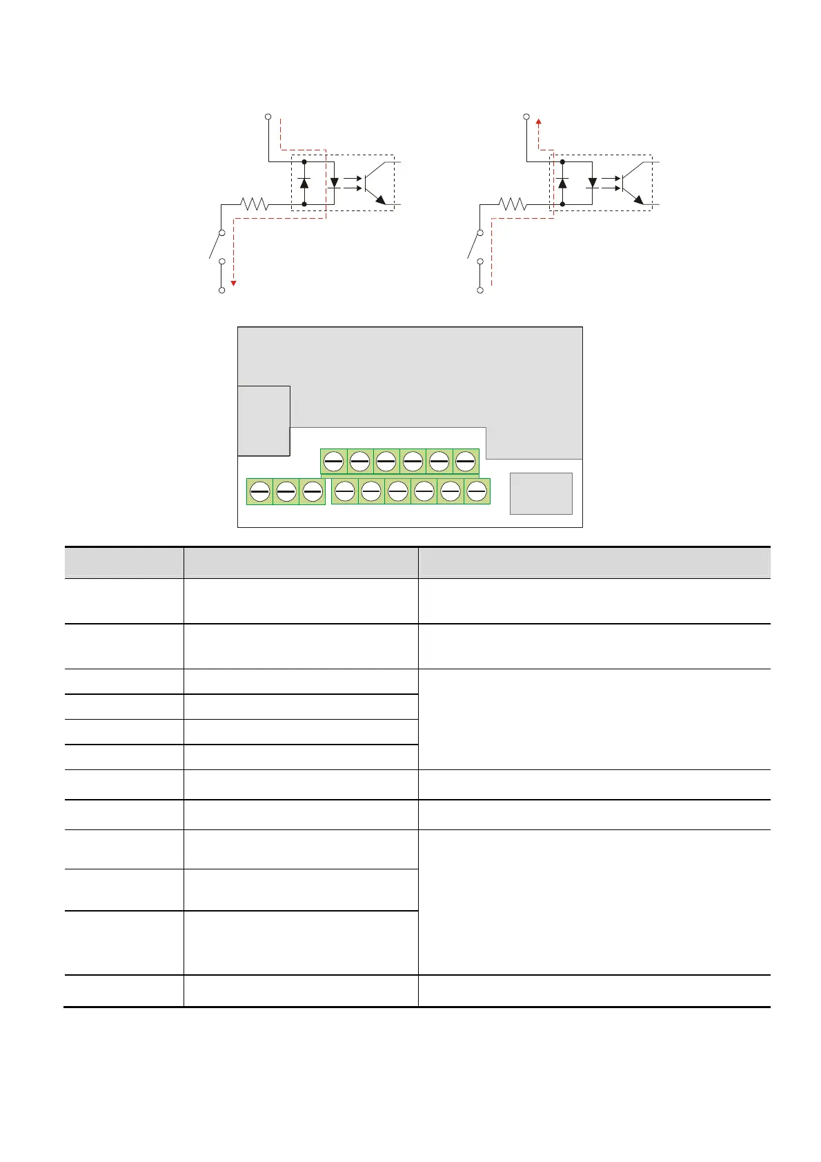
Circuit diagram for digital inputs (NPN current 16mA.)
+24V
1
3
4
2
2
1
The position of the control terminals
MI1 MI3 MI524V AVI
RA
RB
RC
Terminal symbols and functions
Terminal Symbol
Terminal Function Factory Settings (NPN mode) ON: Connect to DCM
MI1 Forward-Stop command
ON: Run in MI1 direction
OFF: Stop acc. to Stop Method
MI2 Reverse-Stop command
ON: Run in MI2 direction
OFF: Stop acc. to Stop Method
MI3 Multi-function Input 3
Refer to Pr.04.05 to Pr.04.08 for programming the
Multi-function Inputs.
ON: the activation current is 5.5mA.
OFF: leakage current tolerance is 10µA.
MI4 Multi-function Input 4
MI5 Multi-function Input 5
MI6 Multi-function Input 6
+24V DC Voltage Source +24VDC, 50mA used for PNP mode.
DCM Digital Signal Common Common for digital inputs and used for NPN mode.
RA Multi-function Relay output (N.O.) a
Resistive Load:
5A(N.O.)/3A(N.C.) 240VAC
5A(N.O.)/3A(N.C.) 24VDC
Inductive Load:
1.5A(N.O.)/0.5A(N.C.) 240VAC
1.5A(N.O.)/0.5A(N.C.) 24VDC
Refer to Pr.03.00 for programming
RB Multi-function Relay output (N.C.) b
RC Multi-function Relay common
+10V Potentiometer power supply +10VDC 3mA