Chapter 4 Parameters|
||
|
4-30 Revision 2016/03, 6ELE, V1.14
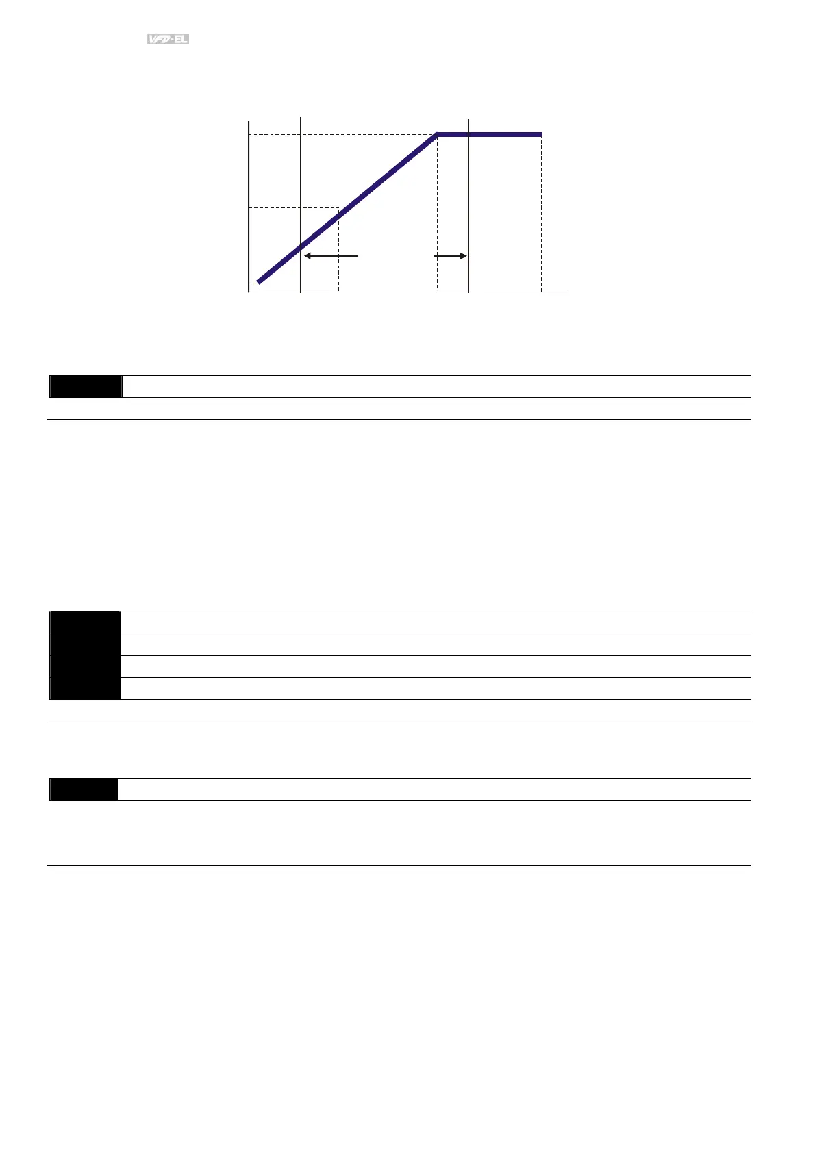
Output Frequency Upper Limit value = (Pr.01.00 * Pr.01.07)/100.
01.05 01.03 01.01
01.06
01.04
01.02
Voltage
Output Frequency
Lower Limit
Output Frequency
Upper Limit
The limit of
Output
Frequency
Mid-point
Freq.
Maximum
Output
Frequency
Maximum
Output
Voltage
Mid-point
Voltage
Minimum
Output
Voltage
Minimum
Output
Freq.
Maximum Voltage
Frequency
(Base Frequency)
01.08
Output Frequency Lower Limit
Unit: 0.1
Settings 0.0 to 100.0% Factory Setting: 0.0
The Upper/Lower Limits are to prevent operation errors and machine damage.
If the Output Frequency Upper Limit is 50Hz and the Maximum Output Frequency is 60Hz, the Output
Frequency will be limited to 50Hz.
If the Output Frequency Lower Limit is 10Hz, and the Minimum Output Frequency (Pr.01.05) is set to 1.0Hz,
then any Command Frequency between 1.0-10Hz will generate a 10Hz output from the drive. If the command
frequency is less than 1.0Hz, drive will be in ready status without output.
This parameter must be equal to or less than the Output Frequency Upper Limit (Pr.01.07).
The Output Frequency Lower Limit value = (Pr.01.00 * Pr.01.08) /100.
01.09
Acceleration Time 1 (Taccel 1) Unit: 0.1/0.01
01.10
Deceleration Time 1 (Tdecel 1) Unit: 0.1/0.01
01.11
Acceleration Time 2 (Taccel 2) Unit: 0.1/0.01
01.12
Deceleration Time 2 (Tdecel 2) Unit: 0.1/0.01
Settings 0.1 to 600.0 sec / 0.01 to 600.0 sec Factory Setting: 10.0
Acceleration/deceleration time 1 or 2 can be switched by setting the external terminals MI3~ MI12 to 7 (set
Pr.04.05~Pr.04.08 to 7 or Pr.11.06~Pr.11.11 to 7).
01.19
Accel/Decel Time Unit
Factory Setting: 0
Settings 0 Unit: 0.1 sec
1 Unit: 0.01 sec
The Acceleration Time is used to determine the time required for the AC motor drive to ramp from 0 Hz to
Maximum Output Frequency (Pr.01.00). The rate is linear unless S-Curve is “Enabled”; see Pr.01.17.
The Deceleration Time is used to determine the time required for the AC motor drive to decelerate from the
Maximum Output Frequency (Pr.01.00) down to 0 Hz. The rate is linear unless S-Curve is “Enabled.”, see
Pr.01.18.
The Acceleration/Deceleration Time 1, 2, 3, 4 are selected according to the Multi-function Input Terminals
Settings. See Pr.04.05 to Pr.04.08 for more details.
In the diagram shown below, the Acceleration/Deceleration Time of the AC motor drive is the time between 0
Hz to Maximum Output Frequency (Pr.01.00). Suppose the Maximum Output Frequency is 60 Hz, Minimum
Output Frequency (Pr.01.05) is 1.0 Hz, and Acceleration/Deceleration Time is 10 seconds. The actual time for
the AC motor drive to accelerate from start-up to 60 Hz and to decelerate from 60Hz to 1.0Hz is in this case
9.83 seconds. ((60-1) * 10/60=9.83secs).