Revision 2016/03, 6ELE, V1.14
B-20
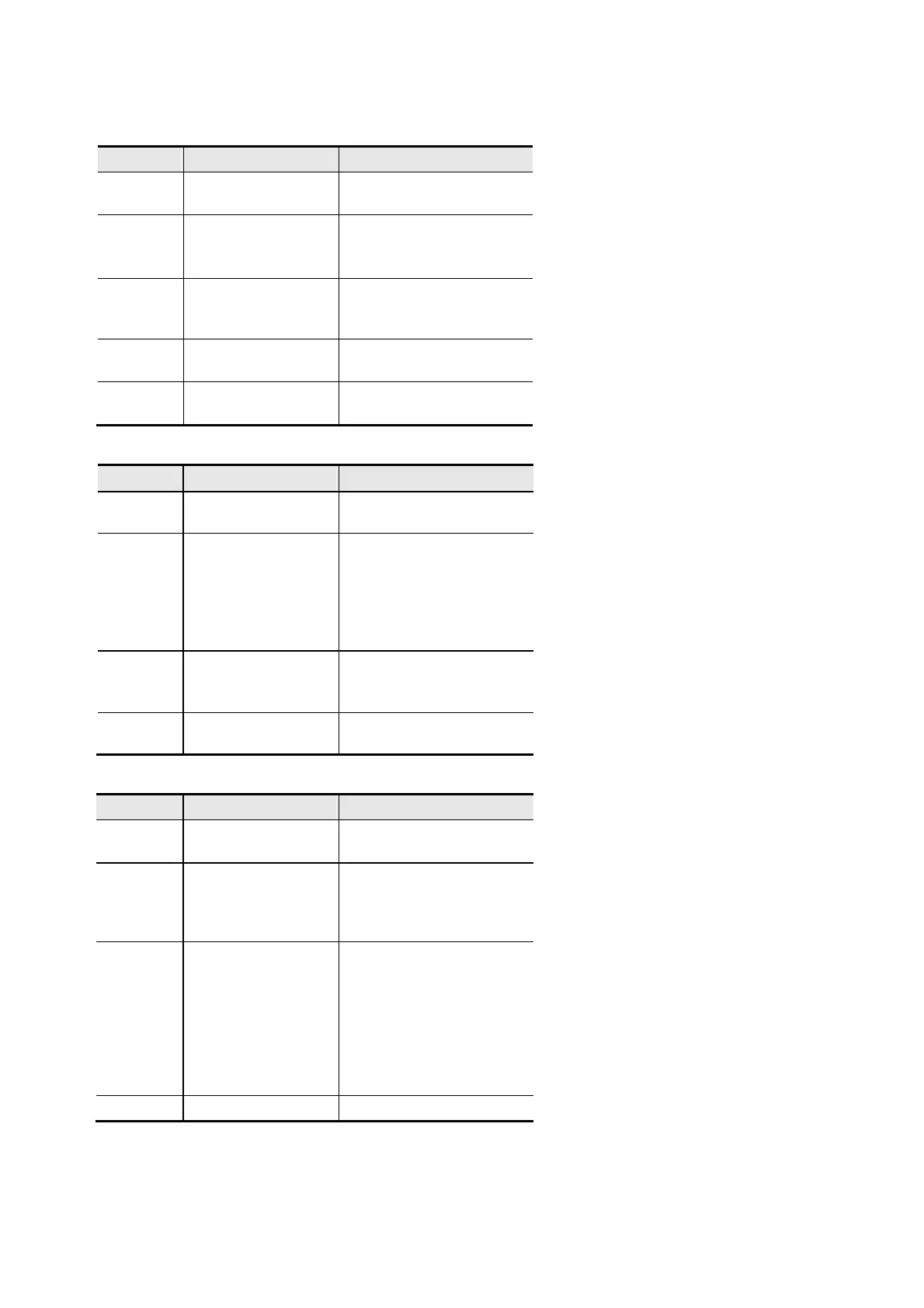
B.8.4.4 LED Indicator Explanation & Troubleshooting
There are 3 LED indicators, RUN, ERROR and SP, on CME-COP01 to indicate the communication status of
CME-COP01.
RUN LED
LED Status
State Indication
OFF No power
No power on CME-
COP01 card
Single
Flash
(Green)
STOPPED
CME-COP01 is in
STOPPED state
Blinking
(Green)
PRE-
OPERATIONAL
CME-COP01 is in the
PRE-OPERATIONAL
state
Green ON
OPERATIONAL
CME-COP01 is in the
OPERATIONAL state
Red ON Configuration error
Node-ID or Baud rate
setting error
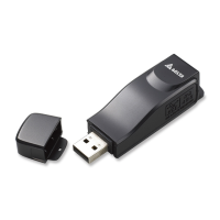
ERROR LED
LED Status
State Indication
OFF No error
CME-COP01 is working
condition
Single
Flash
(Red)
reached
At least one of error
counter of the CANopen
controller has reached or
exceeded the warning
level (too many error
frames)
Double
Flash
(Red)
Error control event
A guard event or
heartbeat event has
occurred
Red ON Bus-off
The CANopen controller is
bus-off
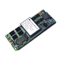
SP LED
LED Status
State Indication
OFF No Power
No power on CME-
COP01 card
LED
Blinking
(Red)
CRC check error
Check your
communication setting in
VFD-EL drives
(19200,<8,N,2>,RTU)
Red ON
connection
1. Check the connection
between VFD-EL drive
and CME-COP01 card
is correct
2. Re-wire the VFD-EL
connection and ensure
that the wire
specification is correct
Green ON
Normal Communication is normal