Chapter 2 Installation and Wiring|
||
|
2-10 Revision 2016/03, 6ELE, V1.14
Terminal Symbol
Terminal Function Factory Settings (NPN mode) ON: Connect to DCM
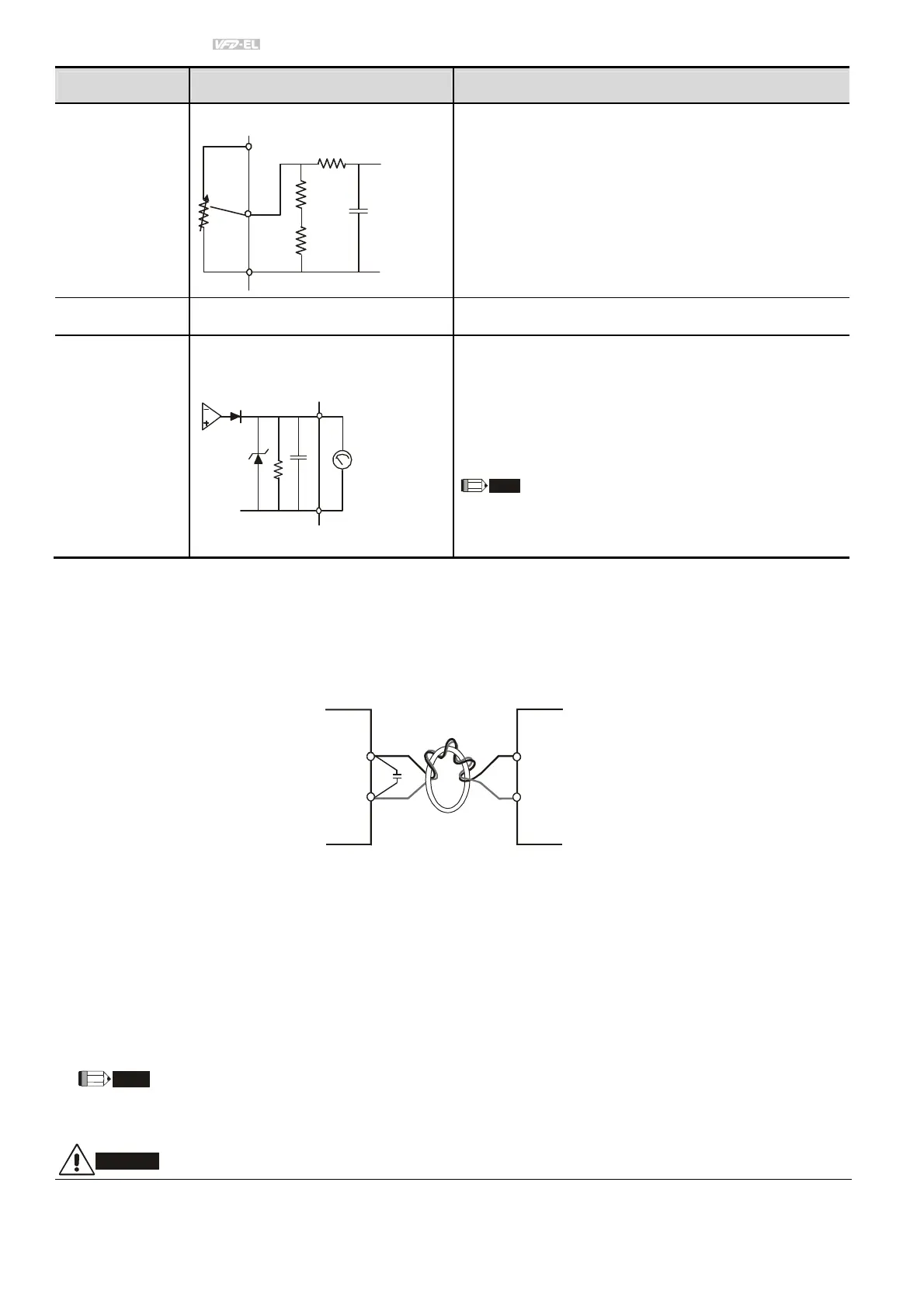
AVI
Analog voltage Input
+10V
AVI circuit
Impedance: 47kΩ
Resolution: 10 bits
Range: 0 ~ 10VDC/4~20mA =
0 ~ Max. Output Frequency (Pr.01.00)
Selection: Pr.02.00, Pr.02.09, Pr.10.00
Set-up: Pr.04.14 ~ Pr.04.17
ACM Analog control signal (common) Common for AVI= and AFM
AFM
Analog output meter
ACM circuit
internal circuit
0 to 10V, 2mA
Impedance: 47Ω
Output current 2mA max
Resolution: 8 bits
Range: 0 ~ 10VDC
Function: Pr.03.03 to Pr.03.04
The voltage output type for this analog signal is PWM. It
needs to read value by the movable coil meter and is
not suitable for A/D signal conversion.
NOTE: Control signal wiring size: 18 AWG (0.75 mm
2
) with shielded wire.
Analog inputs (AVI, ACM)
Analog input signals are easily affected by external noise. Use shielded wiring and keep it as short as
possible (<20m) with proper grounding. If the noise is inductive, connecting the shield to terminal ACM can
bring improvement.
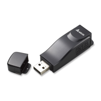
If the analog input signals are affected by noise from the AC motor drive, please connect a capacitor (0.1
F
and above) and ferrite core as indicated in the following diagrams:
C
wind each wires 3 times or more around the core
Digital inputs (MI1~MI6, DCM)
When using contacts or switches to control the digital inputs, please use high quality components to avoid
contact bounce.
General
Keep control wiring as far away as possible from the power wiring and in separate conduits to avoid
interference. If necessary let them cross only at 90º angle.
The AC motor drive control wiring should be properly installed and not touch any live power wiring or
terminals.
If a filter is required for reducing EMI (Electro Magnetic Interference), install it as close as possible to AC
drive. EMI can also be reduced by lowering the Carrier Frequency.
Damaged insulation of wiring may cause personal injury or damage to circuits/equipment if it comes in contact with
high voltage.