Chapter 4 Parameters|
||
|
4-92 Revision 2016/03, 6ELE, V1.14
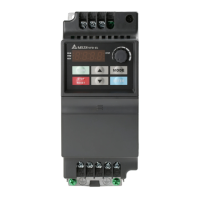
VFD-EL Multi Pumps SOP
STEP
1 PID setting
Pressure feedback signal is only connected to the Master, so only the PID of
the master pump needs to be setup.
Pr10.00 (PID Set Point Selection)
Pr10.01 (Input Terminal for PID Feedback)
2 KP,KI,KD
In a multi-pump system, each invertyer has a PID controller.
All inverters must be setup :
Pr10.02 (KP)
Pr10.03(KI)
Pr10.04(KD)
3 Acceleration/
Deceleration
The acceleration and deceleration time of each inverter has to be setup in a
multi-pump system.
Pr01-09 (Acceleration Time 1)
Pr01-10 (Deceleration Time 1)
4 Keypad Display
The keypad of VFD-EL displays PID setting and feedback signal.
The following parameters have to be setup in each inverter.
Pr00.04 (Content of Multi-function Display)
Set : 5 (Display PID analog feedback signal value in %) or
8 (Display PID setting and feedback signal.)
Pr00.13 (User defined Value 1)
Pr00.14 (Decimal place of user defined Value 1)
Pr10.18 (Feedback of PID physical quantity value)
5
Automatic stop
function
Each inverter must have a function to detect if it is necessary to stop or not to
stop the operation of pumps. The parameters below must be setup:
Pr10.22 (Set Point Deviation Level)
Pr10.23 (Detection Time of Set Point Deviation Level)
Pr01.12 (Deceleration Time 2)
6 Liquid Leakage
Each inverter must have the restart function after liquid leakage and the
related parameters have to be setup.
Pr10.24 (
Offset Level of Liquid Leakage
)
Pr10.25 (
Liquid Leakage Change Detection
)
Pr10.26 (
Time Setting for Liquid Leakage Change
)
7 Multi-pump
function
Distinguish between Master and Slave in accordance of functions required
and set up the parameters respectively.
Note: After setting up the parameters of the Master and Slave. Press the Reset key on the keypad to restart the
Master, then the Master will detect the Slave.