Chapter 2 Installation and Wiring|
||
|
2-2 Revision 2016/03, 6ELE, V1.14
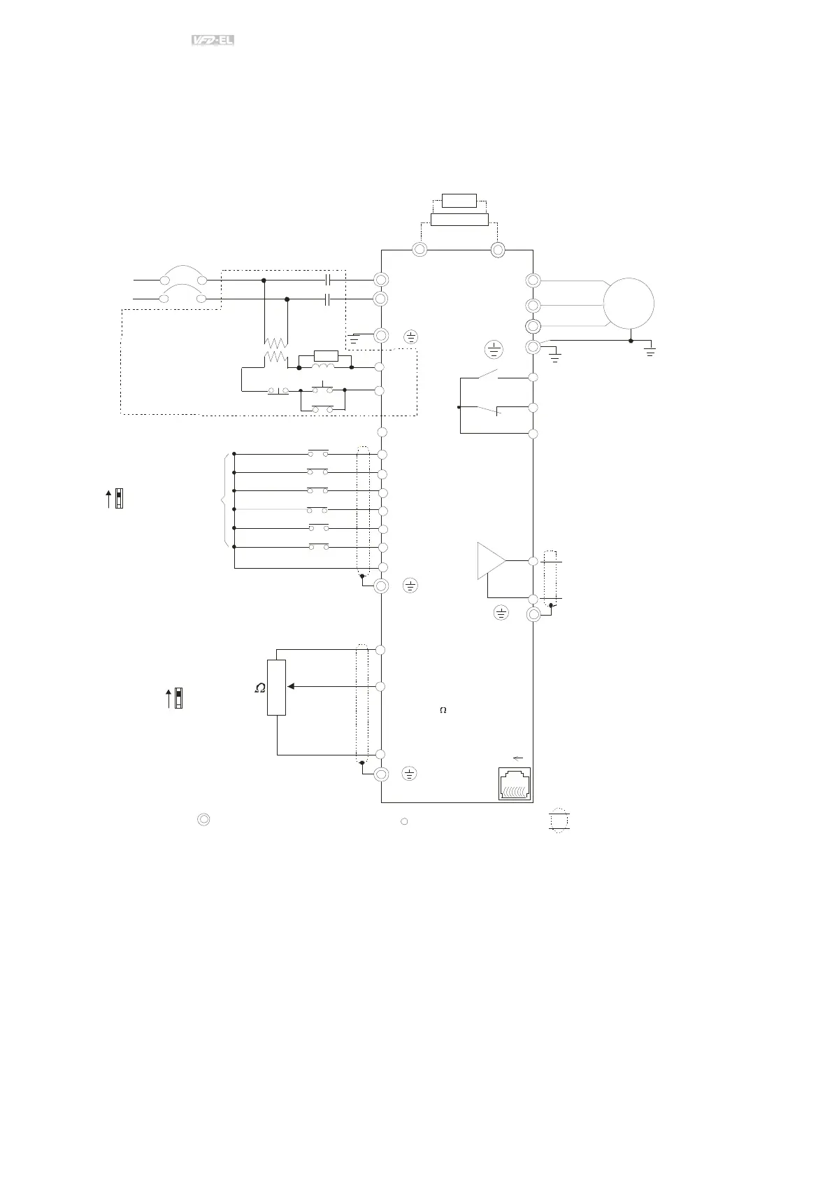
2.1 Wiring
Users must connect wires according to the circuit diagrams on the following pages. Do not plug a modem or
telephone line to the RS-485 communication port or permanent damage may result. The pins 1 & 2 are the power
supply for the optional copy keypad only and should not be used for RS-485 communication.
AVI/ACI
ACM
+
+10V
5K
3
2
1
Figure 1 for models of VFD-EL Series
VFD002EL11A/21A, VFD004EL11A/21A, VFD007EL11A/21A, VFD015EL21A, VFD022EL21A
Power supply
+10V/3mA
Master Fr equency
0- 10V 47K
/4-20mA
Analog S ignal Common
E
Main circ uit (power) terminals
Contr ol c ircuit ter minals
Shielded l eads & Cable
E
R(L1)
S(L2)
F use/NF B(No Fuse B reaker)
SA
OFF
ON
MC
MC
RB
RC
Recommended Circui t
when power suppl y
is tu rned O FF by a
fau lt output
If the fault occ ur s, the
contact will be O N to
turn off th e power and
protect the power sys tem.
R(L1)
S(L2)
E
Analog Multi- func tion Output
Ter minal
Refer to c h apter 2.4 for details .
U(T1)
V(T2)
W(T3)
IM
3~
AFM
ACM
RA
RB
RC
Motor
Analog S ignal common
E
E
MI1
MI2
MI3
MI4
MI6
MI5
DCM
+24V
FWD/Stop
REV/Stop
Multi-s tep 1
Multi-s tep 2
Multi-s tep 3
Multi-s tep 4
Digital Si gnal Common
Fac tor y
set ting
AVI
ACI
F act ory settin g:
AVI Mo de
-
RS-485
Seri al interface
1: R eserv ed
2: EV
5: SG +
6: R eserv ed
7: R eserv ed
8: R eserv ed
3: G ND
4: SG -
8
1
Sw1
NPN
PNP
F act ory settin g:
NPN Mo de
Please refer to F ig ur e 3
fo r w irin g of NPN
mod e an d PNP
mod e.
BUE
brake unit
(optional)
BR
brake resi stor
(opti onal)
Multi-f unction c ontact output
Refer to c hapter 2.4 for details .
F ac tor y setting is
malfunction indication
F actor y setting: output frequency
Sw2