Revision 2016/03, 6ELE, V1.14
B-2
1. If damage to the drive or other equipment is due to the fact that the brake resistors and the brake modules
in use are not provided by Delta, the warranty will be void.
2. Take into consideration the safety of the environment when installing the brake resistors.
3. If the minimum resistance value is to be utilized, consult local dealers for the calculation of the power in
Watt.
4. Please select thermal relay trip contact to prevent resistor over load. Use the contact to switch power off to
the AC motor drive!
5. When using more than 2 brake units, equivalent resistor value of parallel brake unit can’t be less than the
value in the column “Minimum Equivalent Resistor Value for Each AC Drive” (the right-most column in the
table).
6. Please read the wiring information in the user manual of the brake unit thoroughly prior to installation and
operation.
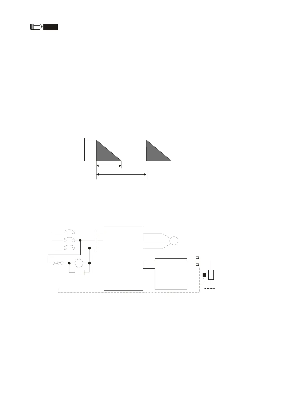
7. Definition for Brake Usage ED%
Explanation: The definition of the barke usage ED(%) is for assurance of enough time for the brake unit
and brake resistor to dissipate away heat generated by braking. When the brake resistor heats up, the
resistance would increase with temperature, and brake torque would decrease accordingly. Suggested
cycle time is one minute
100%
T0
T1
Braking Time
Cycle Time
ED% = T1/T0x100(%)
8. For safety reasons, install a thermal overload relay between brake unit and brake resistor. Together with
the magnetic contactor (MC) in the mains supply circuit to the drive it offers protection in case of any
malfunctioning. The purpose of installing the thermal overload relay is to protect the brake resistor against
damage due to frequent brake or in case the brake unit is continuously on due to unusual high input
voltage. Under these circumstances the thermal overload relay switches off the power to the drive. Never
let the thermal overload relay switch off only the brake resistor as this will cause serious damage to the AC
Motor Drive.
R/L1
S/L2
T/L3
MC
VFD Series
MOTOR
O.L.
U/T1
V/T2
W/T3
+ P
- N
( )
( )
B1
B2
SA
R/L1
S/L2
T/L3
MC
IM
BR
O.L.
Thermal
Overload
Relay or
temperature
switch
Surge
Absorber
Thermal Overload
Relay
Brake
Resistor
Brake
Unit
+ P
- N
( )
( )
Note1: When using the AC drive with DC reactor, please refer to wiring diagram in the AC drive
user manual for the wiring of terminal +(P) of Brake unit.
Note2: wire terminal -(N) to the neutral point of power system.Do NOT
Temperature
Switch