Revision 2016/03, 6ELE, V1.14
2-5
1.
The wiring of main circuit and control circuit should be separated to prevent erroneous actions.
2.
Please use shield wire for the control wiring and not to expose the peeled-off net in front of the terminal.
3.
Please use the shield wire or tube for the power wiring and ground the two ends of the shield wire or tube.
4.
Damaged insulation of wiring may cause personal injury or damage to circuits/equipment if it comes in contact
with high voltage.
5.
The AC motor drive, motor and wiring may cause interference. To prevent the equipment damage, please take
care of the erroneous actions of the surrounding sensors and the equipment.
6.
When the AC drive output terminals U/T1, V/T2, and W/T3 are connected to the motor terminals U/T1, V/T2, and
W/T3, respectively. To permanently reverse the direction of motor rotation, switch over any of the two motor leads.
7.
With long motor cables, high capacitive switching current peaks can cause over-current, high leakage current or
lower current readout accuracy. To prevent this, the motor cable should be less than 20m for 3.7kW models and
below. And the cable should be less than 50m for 5.5kW models and above. For longer motor cables use an AC
output reactor.
8.
The AC motor drive, electric welding machine and the greater horsepower motor should be grounded separately.
9.
Use ground leads that comply with local regulations and keep them as short as possible.
10.
No brake resistor is built in the VFD-EL series, it can install brake resistor for those occasions that use higher load
inertia or frequent start/stop. Refer to Appendix B for details.
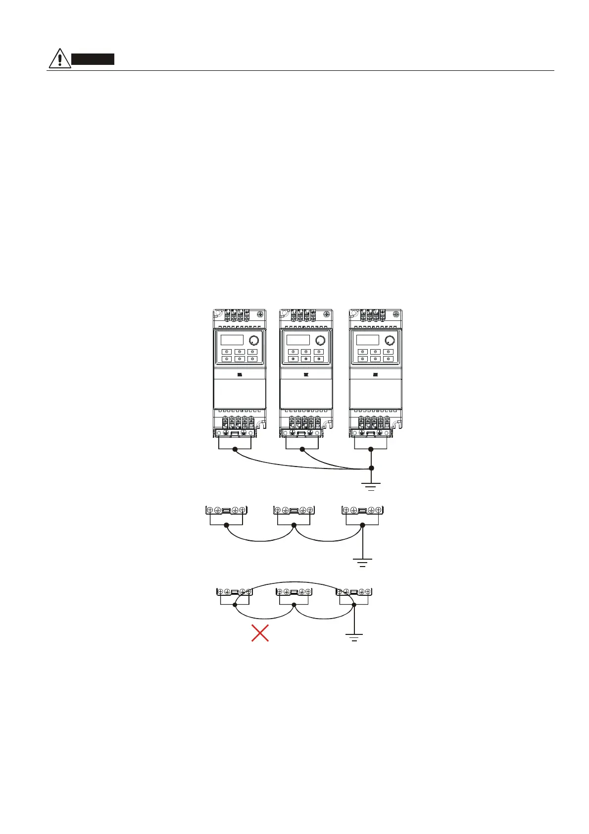
11.
Multiple VFD-EL units can be installed in one location. All the units should be grounded directly to a common
ground terminal, as shown in the figure below. Ensure there are no ground loops.