AS64AM10N-A
8
9
92
75
8
88
98.3
1
4
5
2
3
6
2
X0
64AM
40
X1
1
0
0
9
8
4
5
6
7
3
15
14
2
10
12
11
13
40
X3
2
PWR
IN
0
1
X2
0
1
1
7
38.2
35
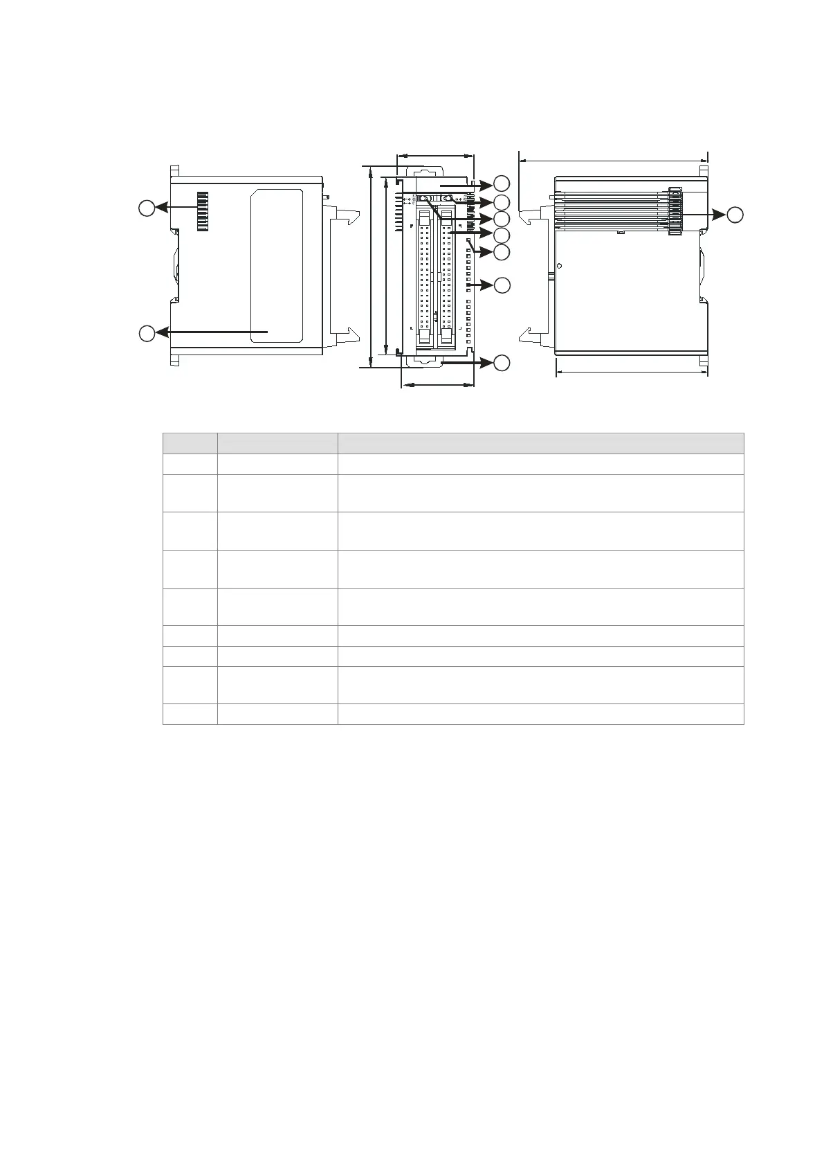
Unit: mm
2
LED indicator
Switches the LED indicators to their represented inputs.
3
LED indicator
Switches the LED indicators to their represented inputs.
4 ML connector
For the external I/O connecting cables UC-ET010-24B, UC-ET020-
5
Power LED
Indicates the power status of the module
If there is an input signal, the input LED indicator is ON.
8
External module
port
Connects the modules
9 Label Nameplate
Send Quote Requests to info@automatedpt.com
Call +1(800)985-6929 To Order or Order Online At Deltaacdrives.com
Send Quote Requests to info@automatedpt.com
Call +1(800)985-6929 To Order or Order Online At Deltaacdrives.com
 Loading...
