AX-Series Motion Controller Instructions Manual Chapter 2
141
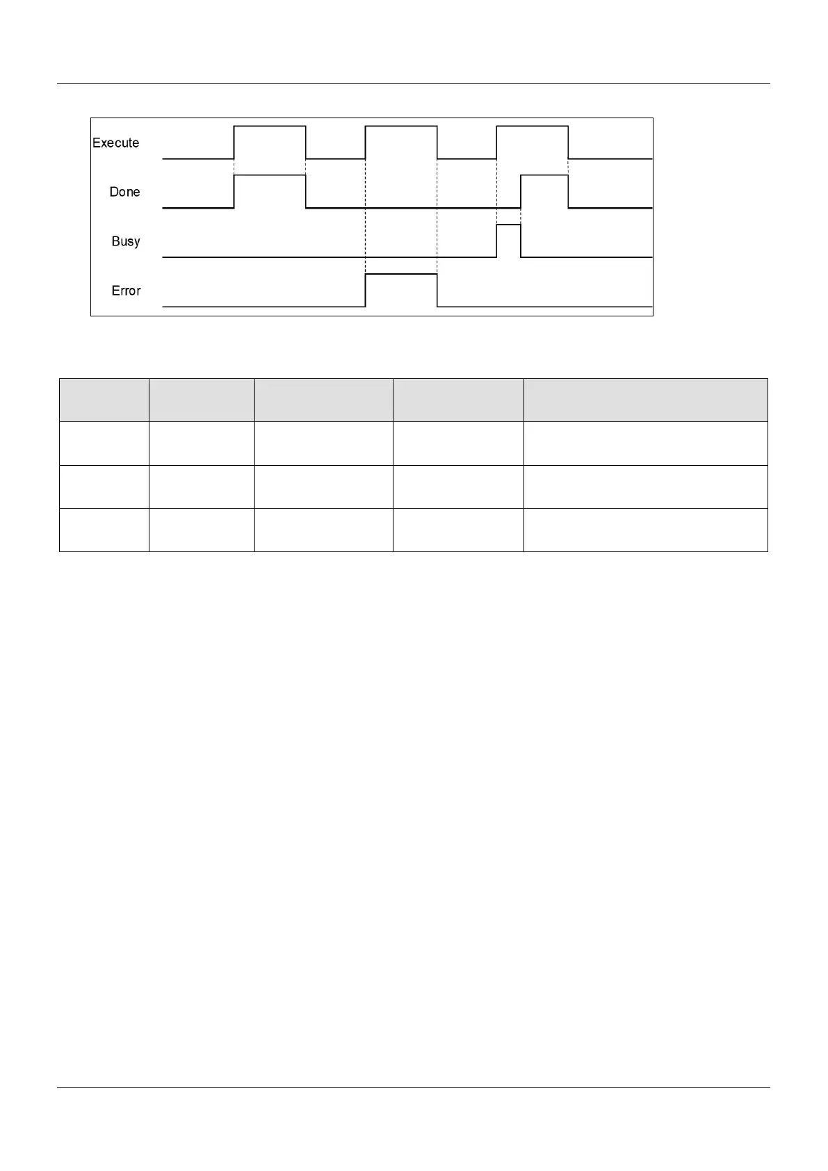
Timing Diagram
Inputs/Outputs
Name Function Data Type
Setting Value
Timing to Take Effect
Master
Specifies the
AXIS_REF_SM3*
1
AXIS_REF_SM3
When Execute turns to True and Busy is
Slave
Specifies the
AXIS_REF_SM3*
1
AXIS_REF_SM3
When Execute turns to True and Busy is
CamTable
Specifies cam
MC_CAM_REF*
2
MC_CAM_REF
When Execute turns to True and Busy is
*Note:
1. AXIS_REF_SM3(FB): Every function block contains this variable, which works as the starting program for function blocks.
2. MC_CAM_REF(FB): This data structure is used as reference to a cam table specified by users.
Function
Use MC_CamTableSelect to select the cam table for operation.
Set Execute to be True so as to execute the specified or refreshed cam table. When Done turns to True, CamTableID
is effective.
After the master-slave synchronization is completed, the modification of MC_CamTableSelect parameters can cause
changes in the cam behavior.
After changes the variables of CamTable, the mode of cam behavior will be effective immediately.
The function block must be reboot after changing Periodic mode.
Troubleshooting
If an error occurs during the execution of the instruction, Error will change to True. You can refer to ErrorID (Error Code)
to address the problem.
Example
The following example explains the impact on cam after changing Periodic mode.
Timing Diagram
 Loading...

