8 | Components description
132 AXH1230‐UK ﴾ENG﴿ ‐ Apollo KM
Formoreinformation,refertothe"Capacitydiagramslegend"chapter.
3
Capacity Diagram code
4
Equipment maximum capacity
ThemaximumCapacityoftheequipmentisalsoreportedbythestickerplacedontheequipment
itself.
5
Boom angle
Theboomangleisindicatedbytheinclinometerontheleftsideattheendoftheboom(ifany),or
onthedisplayoftheantitippingdevice(ifpresent).
6
Boom extension
Theboomextensionisindicatedbylettersofthealphabet(“A”,“B”,"C","D",etc...).Thesamelettersare
shownasstickersontheboomextension,sothattheuserinthecabcanknowtheboomextension
byreadingthelettersonit.
7
Machine operating mode
Formoreinformation,refertothe"Capacitydiagramslegend"chapter.
8
Load height from ground
9
Horizontal distance of the machine load
10
Load weight
11
Machine position
8.18.1.2 Use the capacity diagrams
Thecapacitydiagramsindicatetheareasinwhichitispossibletooperatewiththemachineandloadinsafe
conditions.
DANGER
Danger of tipping.
Operating the machine without observing the Capacity diagrams related to the equipment installed may
result in hazardous conditions, up to the tipping limit and the operation of the Anti-tipping device.
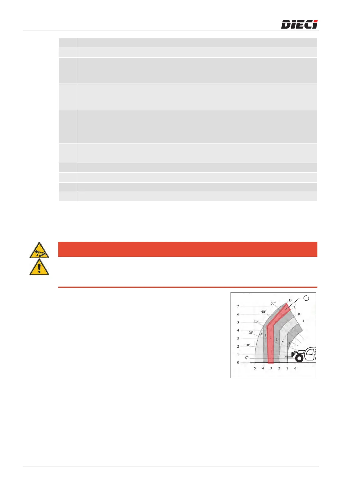
Thewholeworkingareaoftheboomisdividedintotheseareas
(position “1”, fig. 1504651). Each area corresponds to a
maximumcapacity.Theareaclosesttothemachinewillhavea
capacityequaltothemaximumloadingcapacityofthemachine;
asmovingawayfromthemachine,themaximumcapacityofthe
areasdecreases.
Beforestartingtowork,itisnecessarytoknow:
– Loadweight
– Heightfromgroundatwhichtheloadmustbehandled
– Distance from the machine at which the load must be
handled
Locate the area of the capacity diagram, showing a value just
abovetheweightoftheloadtobehandled;forexampleifthe
loadshouldweigh1.5tons,theareatowhichitisnecessaryto
referistheareawithacapacityof2tons(position“1”).
150465-1