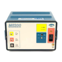
Sweep Frequency Response Analyzer (SFRA) User Guide
Index-4 72A-2570-01 Rev. K 07/2011
reports, configuring and printing 5-16
resistance between ground connections 3-22
Responses for One Phase of a Transformer
HV Delta Trace (screenshot) 3-26
results see test results
RLC network measured by SFRA C-5
S
safety requirements 2-1
ground cable photo and part number 1-3
ground connection, example of 2-2
grounding instructions for transformers
3-12
personnel 2-3
sample test results 3-25
saving traces 5-11
Select Apparatus command, defined A-7
Select Default Template Window A-4
Select Installation Folder Window
(screenshot) A-2
Select Instrument window (Screenshot) 3-3
selecting a folder for viewing data 5-9
serial numbers of SFRA instruments, adding
SFRA 5.2 database 5-3
settings files 5-12
merging 5-14
SFRA 1.x and 2.x, importing files from 5-12
SFRA 5.2 software
adding tap changer data 5-7
importing SFRA 1.x and 2.x files 5-12
installing A-1
measurement of RLC network C-5
organization information 5-4
RLC network measurement C-5
test instrument information 5-3
transformer information 5-5
SFRA instrument
cable connections 3-2
repairing D-3
replacement parts D-3
startup indicator lights 3-3
theory of operation C-1
SFRA testing, defined 1-1
shipping address of Doble D-3
Short Circuit Trace – Detail (screenshot) 3-28
short-circuit measurement, defined 3-1
short-circuit response, sample 3-25
Short-Circuit Test Trace (screenshot) 3-28
Shorted Turn on One Winding (screenshot)
3-30
shorted turn sample responses 3-29
shorted-lead test
auto-zoom of traces 3-10
connections for measurement leads and
reference grounds 3-9
correct response 3-11
open-circuit lead response 3-11
setting up and running 3-2
Shorted-Lead Test in Progress (screenshot)
3-10
Simplified XML Transformer Settings File
(screenshot) 5-13
standard test lead with photo and part number
1-3
Start Menu (screenshot) 3-30
Start Test command, defined A-7
Status Bar (screenshot) A-12, A-13, A-14
Sub-Band tab A-15
Sweep Frequency Response Analyzer Settings
(screenshot) 5-8
Sweep Frequency Response Analyzer Settings
Dialog Box (screenshot) 5-9
system OK indicator light 3-3
T
tabs
Analysis A-17
Apparatus A-19
Data Manager A-11
Impedance A-14
Magnitude A-12
Phase A-13

 Loading...