A
B
C
D
E
F
G
H
L
M
N
P
Comandi - Dispositivi
Controls - Devices
sezione / section
F 3
16
edizione/edition 03-03
Attenzione
La casa costruttrice della
pompa freno, considerando
l’importanza in termini di sicurezza
che riveste questo componente,
suggerisce di non intervenire in
nessun modo all’interno della pompa.
Una revisione non eseguita
correttamente può mettere in serio
pericolo l’incolumità del pilota.
Le operazioni di sostituzione si
devono limitare alla leva di comando,
al gruppo serbatoio con relativi
componenti di fissaggio e al fissaggio
pompa.
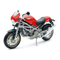
Smontaggio pompa freno
idraulico anteriore
Svitare le viti (8) di fissaggio e
rimuovere il gruppo pompa freno
anteriore (5) dal semimanubrio.
Per la scomposizione dei componenti
del gruppo pompa (5) fare riferimento
all’esploso riportato a inizio capitolo.
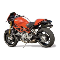
Rimontaggio pompa
freno idraulico anteriore
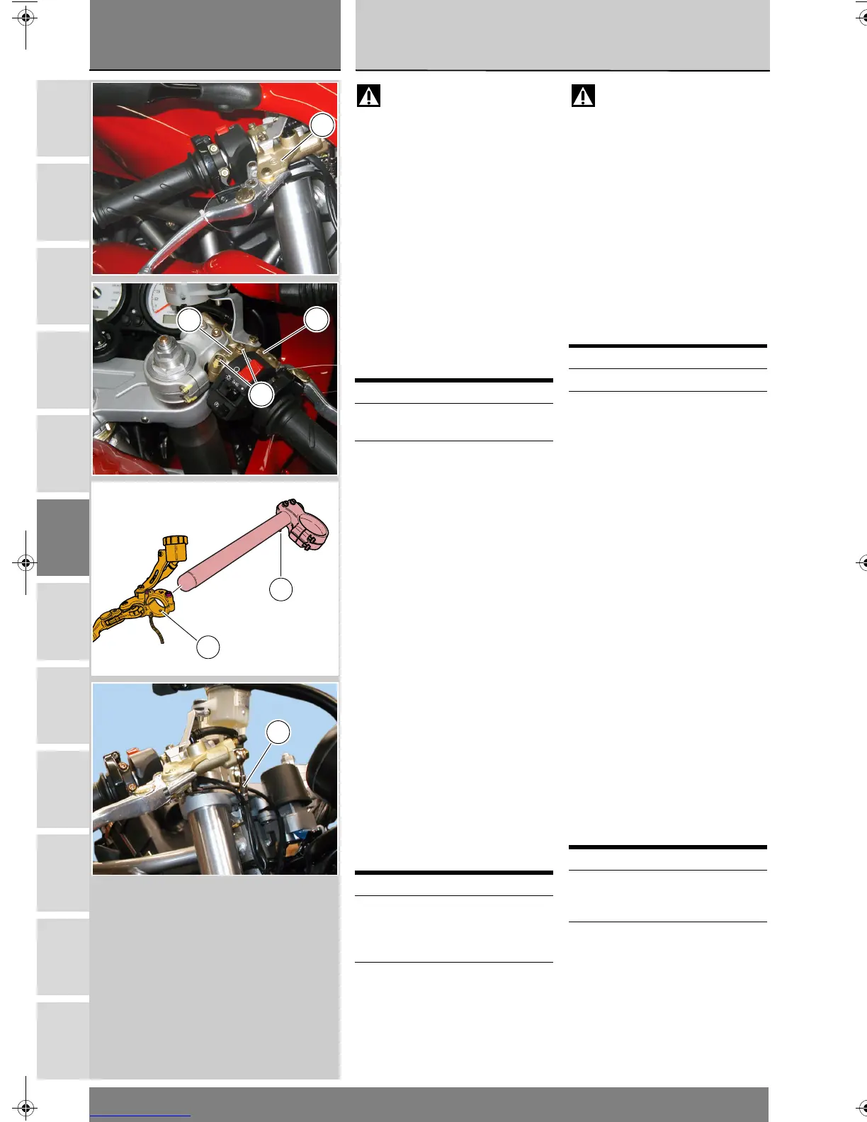
Posizionare il perno di riferimento (A)
sul corpo pompa (5) nell’apposito foro
(B) ricavato nel semimanubrio.
Avvitare le due viti (8) del cavallotto
(7) di fissaggio pompa freno anteriore
sul manubrio.
Serrare le viti (8) alla coppia prescritta
(Sez. C 3) partendo da quella superiore
e poi procedendo con sequenza 1-2-1.
Nel caso si sia intervenuti sulla
tubazione (C), seguire quanto
riportato alla Sez. G 3.
Operazioni Rif. Sez.
Svuotare l’impianto
frenante
D 4
Scollegare il tubo
comando freno
anteriore dal gruppo
pompa
G 3
Operazioni Rif. Sez.
Ricollegare il tubo
comando freno
anteriore al gruppo
pompa
G 3
Riempire l’impianto
frenante
D 4
Warning
Critical safety components. The
brake master cylinder manufacturer
recommends that you do not attempt
to service the internal components of
brake master cylinder. Incorrect
overhaul of this critical safety
component can endanger rider
safety.
Maintenance operations on these
units are limited to replacing: control
lever, reservoir unit and reservoir and
cylinder fasteners.
Removing the front brake
master cylinder
Unscrew the retaining screws (8) and
remove the front brake master
cylinder assembly (5) from the
handlebar.
Please refer to the exploded view at
the beginning of this section for
indications on disassembly of master
cylinder (5) components.
Refitting the front brake
control
Position the locating peg (A) onto the
cylinder body (5) into the hole (B) in
handlebar.
Fit the two screws (8) of the U-bolt (7)
securing the front brake cylinder to
the handlebar.
Tighten the screws (8) to the
specified torque (Sect. C 3) starting
from the upper one and then working
in a 1-2-1 sequence.
Follow indications as specified under
Section G 3 if tube (C) needs some
servicing.
Operations See Sect.
Drain the brake system D 4
Disconnect the front
brake hose from master
cylinder
G 3
Operations See Sect.
Connect the front
brake hose to master
cylinder
G 3
Fill the brake system
with fluid
D 4
5
5
7
8
A
B
C
'8&PRB66B)EERRN3DJH7KXUVGD\0DUFK30