A
B
C
D
E
F
G
H
L
M
N
P
Mototelaio
Frame
sezione / section
H 4
14
edizione/edition 03-03
Rimontaggio pedane
Le operazioni di rimontaggio di
seguito descritte sono analoghe sia
per la piastra portapedana anteriore
destra (1) che per la piastra
portapedana anteriore sinistra (16) e
sia per la piastra portapedana
posteriore destra (12) che per la
piastra portapedana posteriore
sinistra (18).
Per quanto riguarda il lato destro
posteriore del motoveicolo,
posizionare la molla (8), i piastrini (7),
le sferette (9) e la pedana (6) tra le
battute della piastra (12).
Introdurre dal lato superiore il perno
(14) opportunamente ingrassato e
bloccarlo sul lato opposto con l’anello
(15).
Effettuare la stessa operazione per il
lato sinistro posteriore.
Per quanto riguarda il lato destro
anteriore del motoveicolo,
posizionare la molla (3) tra le battute
della pedana (13) e montarla sulla
piastra (1), inserendo l’estremità
rettilinea della molla nel foro della
piastra.
Introdurre dal lato superiore il perno
(2) opportunamente ingrassato e
bloccarlo sul lato opposto con l’anello
(4).
Effettuare la stessa operazione per il
lato sinistro anteriore.
Posizionare la piastra anteriore destra
(1), la piastra anteriore sinistra (16), la
piastra posteriore destra (12) e la
piastra posteriore sinistra (18) sul
telaio e impuntare le viti (5).
Serrare le viti (5) alla coppia prescritta
(Sez. C 3).
Dopo aver montato le piastre
posteriori (12) e (18) sul telaio, fissarle
ai silenziatori mantenendo i gommini
(E) sulle staffe ed infilare le
colonnette (D) e le viti (B), serrando le
viti alla coppia prescritta (Sez. C 3) sui
dadi (C).
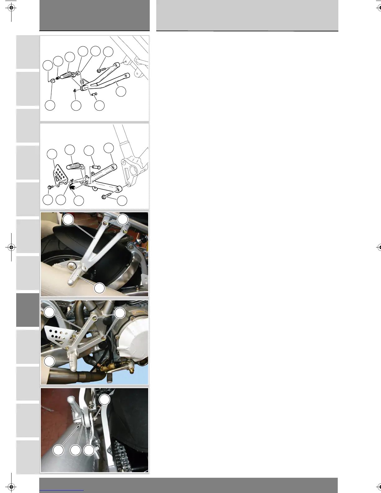
Refitting the footpegs
The following reassembly procedure
applies to right front footpeg holder
plate (1) and left front footpeg holder
plate (16) as well as to right rear
footpeg holder plate (12) and left rear
footpeg holder plate (18).
When working on vehicle rear right
side, position spring (8), plates (7),
balls (9) and footpeg (6) between
plate (12) end stops.
Thoroughly grease pin (14) and,
working from top, lock it on the
opposite side with ring (15).
Repeat the same procedure on the
rear left side.
When working on vehicle front right
side, position spring (3) between
footpeg (13) end stops and, to install
it on plate (1), insert spring straight
side inside plate hole.
Thoroughly grease pin (2) and,
working from top, lock it on the
opposite side with ring (4).
Repeat the same procedure on the
front left side.
Position right front plate (1), left front
plate (16), right rear plate (12) and left
rear plate (18) on frame and start
screws (5) into their threads.
Tighten screws (5) to the specified
torque (Sect. C 3).
Fit the rear plates (12) and (18) onto
the frame, keep rubber blocks (E)
onto the brackets and fit the stud
bolts (D) and the screws (B) to secure
to the silencers and then tighten to
the specified torque (Section C 3) to
the nuts (C).
9
8
6
7
7
9
5
14
12
15
5
11
10
13
2
1
3
4
12 5
6
5
13
1
E
C
DB
'8&PRB66B+EERRN3DJH:HGQHVGD\0DUFK30
 Loading...