A
B
C
D
E
F
G
H
L
M
N
P
Ruote - Sospensioni - Freni
Wheels - Suspensions - Brakes
sezione / section
G 6
34
edizione/edition 03-03
Smontaggio impianto
freno posteriore
Importante
La casa costruttrice delle pinze,
considerando l'importanza in termini
di sicurezza che riveste questo
componente, suggerisce di non
intervenire in nessun modo all'interno
della pinza. Una revisione non
eseguita correttamente può mettere
in serio pericolo l'incolumità del pilota.
Le operazioni di sostituzione si
devono limitare alle pastiglie, ai
componenti di fissaggio e al gruppo di
spurgo.
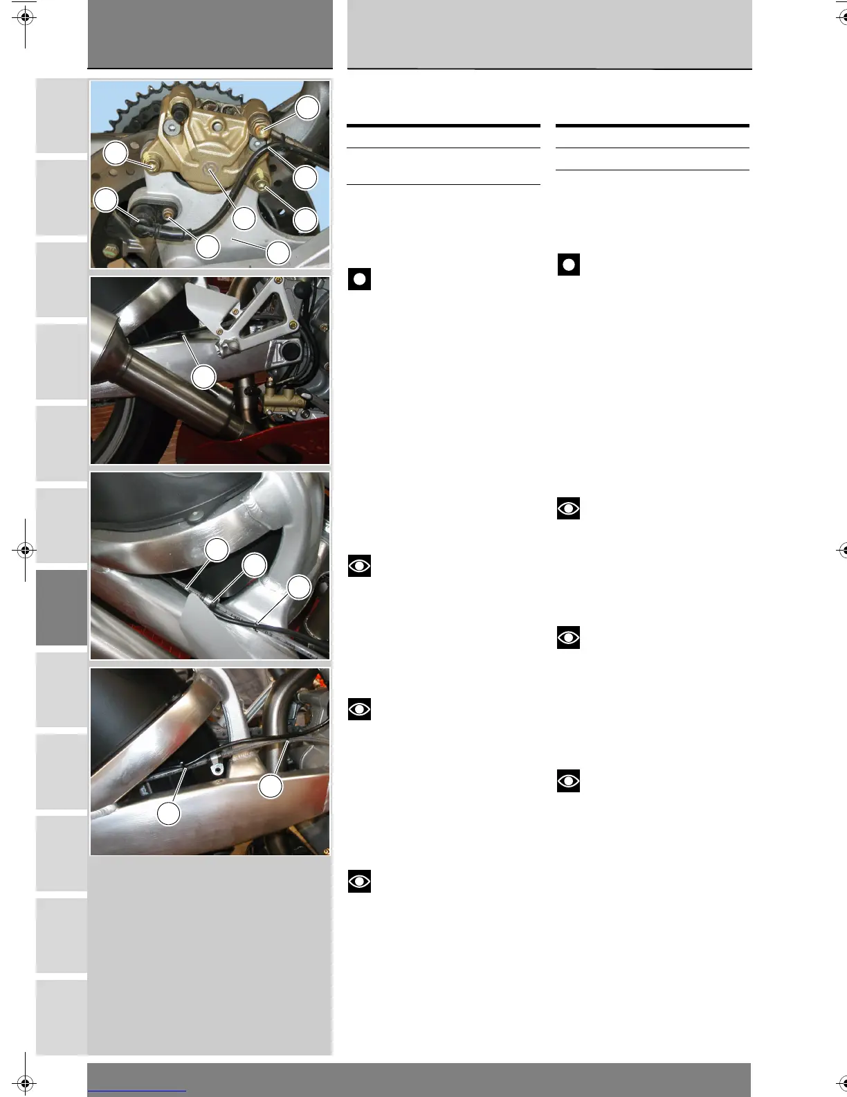
Svitare e rimuovere la vite speciale (1)
di fissaggio della tubazione (A) alla
pinza freno posteriore e le relative
guarnizioni (2).
Note
Tenere a disposizione uno
straccio per l’eventuale fuoriuscita di
olio freni dal tubo.
Svitare la vite (7) di fissaggio tubo
freno sul forcellone.
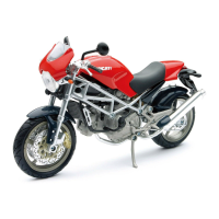
Rimuovere la tubazione (A), completa
di graffetta (12).
Note
Prima di rimuovere la pinza
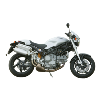
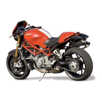
freno (3), rimuovere le fascette (B),
che fissano il cavo del sensore ruota
posteriore al tubo freno.
Svitare le due viti (5) di fissaggio pinza
freno posteriore, alla piastra
portapinza.
Rimuovere la pinza freno (3).
Note
Per le operazioni di sostituzione
delle pastiglie freno seguire quanto
riportato al paragrafo “Controllo usura
e sostituzioni pastiglie freno” della
sezione D 4.
Per rimuovere il sensore velocità (13),
svitare la vite (14) di fissaggio alla
piastra portapinza, facendo
attenzione al distanziale (6).
Operazioni Rif. Sez.
Svuotare l’impianto
frenante
D 4
Rimuovere vite di
fissaggio tubazione alla
pompa freno posteriore
e guarnizioni
F 4
Removing the rear brake
system
Caution
Critical safety components. The
brake caliper manufacturer
recommends that you do not attempt
to service the internal components of
brake calipers. Incorrect overhaul of
these critical safety components can
endanger rider safety.
Only the following parts should be
replaced:
pads, fasteners and bleed unit.
Release and remove the special
screw (1) retaining the hose (A) to the
rear brake caliper and the seals (2).
Note
Always keep a cloth at hand to
clean off any brake fluid leaking out.
Undo the brake hose retaining screw
(7) on the swingarm.
Remove the hose (A) together with
the retainer (12).
Note
Before removing brake caliper
(3), remove ties (B) fixing rear wheel
sensor cable to brake line.
Unscrew the two screws (5) that
retain the rear brake caliper to the
caliper mounting plate.
Remove the caliper (3).
Note
See paragraph "Checking brake
pad wear. Changing brake pads" in
Section D 4 for instructions on how to
change the brake pads.
To remove the speed sensor (13),
unscrew the screw (14) retaining the
sensor to the caliper mounting plate
and collect the spacer (6).
Operations See Sect.
Drain the brake circuit D 4
Remove the screw
retaining the hose to
the rear brake cylinder
and the seals
F 4
5
3
1
5
14
13
A
4
7
A
12
B
B
B
'8&PRB66B*EERRN3DJH7KXUVGD\0DUFK30










 To Next Page