A
B
C
D
E
F
G
H
L
M
N
P
Motore
Engine
sezione / section
N 9.2
146
edizione/edition 03-03
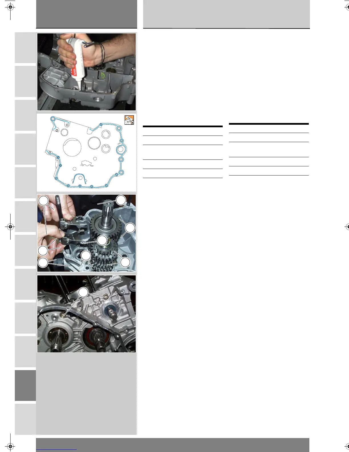
Applicare il cordone uniforme e
continuo di pasta sigillante DUCATI
sulla superficie di accoppiamento dei
semi carter, contornando tutti i fori,
come mostrato in figura.
Accoppiare i semicarter (3) e (13)
eventualmente battendo con martello
in gomma in prossimità degli alberi.
Preparare le viti di fissaggio
lubrificandole, con grasso prescritto,
ed impuntarle sul semicarter lato
alternatore, facendo attenzione alle
differenti lunghezze.
Avvitare fino in battuta in modo
progressivo le viti di unione, partendo
da quelle di diametro maggiore (M8).
Installare due viti M8 (12), sul lato
frizione.
Serrare tutte le viti, partendo da
quelle di diametro maggiore, alla
coppia di serraggio prescritta (Sez. C
3).
Controllare che l'albero motore ruoti
con una certa interferenza sui
cuscinetti di banco (l'albero motore
deve avere un precarico di 0,20 ÷ 0,30
mm) e che tutti gli organi montati
ruotino o si spostino correttamente.
Rif. Q.tà Descrizione
12-28 6 viti M8x75 mm
26 1 vite forata M8x75
mm
24 7 viti M6x35 mm
27 2 viti M6x75 mm
Apply a uniform bead of DUCATI
liquid gasket on the mating surface of
the casing, avoiding the holes as
shown in the figure.
Match the casings (3) and (13). Tap
the area around the shafts with a
plastic hammer, if necessary.
Grease the jointing screws with
recommended grease and start them
into their holes on the generator-side
casing. The screws are not all the
same length, be sure to position them
correctly.
Progressively tighten the jointing
screws all the way in. Begin with the
larger diameter (M8) screws.
Fit two M8 screws (12) on the clutch
side casing.
Tighten all screws to the specified
torque (Sect. C 3). Begin with the
larger diameter screws.
Check that crankshaft rotates with a
certain amount of interference in the
main bearings. Crankshaft must have
a pre-load of 0.20 - 0.30 mm. Check
also that all assembled parts can
rotate or move correctly.
Ref. Q.ty Description (mm)
12-28 6 M8x75 screws
26 1 M8x75 drilled
screw
24 7 M6x35 screws
27 2 M6x75 screws
28
28
27
24
24
24
26
24
12
'8&PRB66B1EERRN3DJH:HGQHVGD\0DUFK$0