M588-08-880 Issue D
Page 102 © Edwards Limited 2017. All rights reserved.
Edwards and the Edwards logo are trademarks of Edwards Limited.
Digital pressure measurements
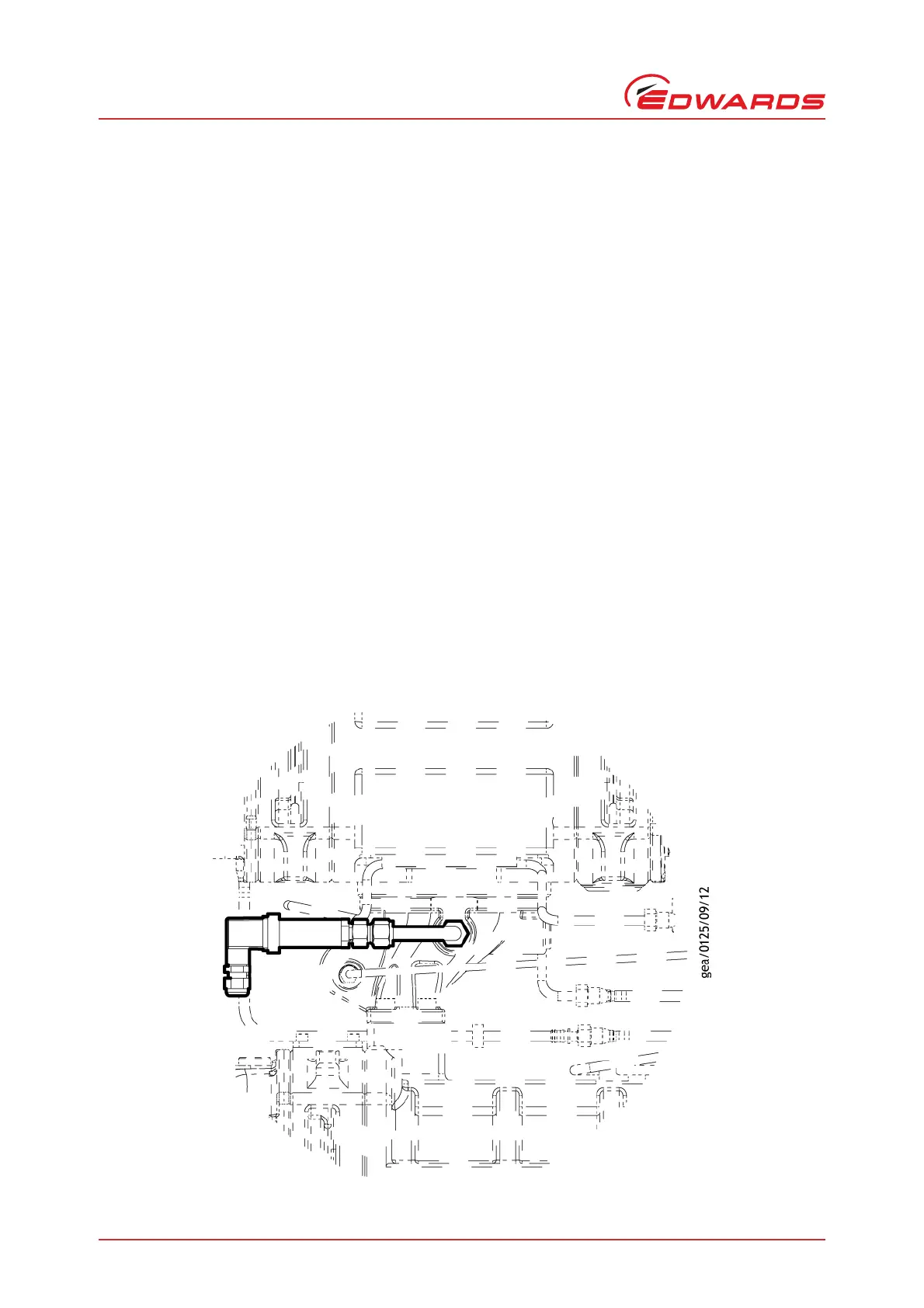
8.3.4 Installation of the pressure transducer assembly to the internally mounted pump
interspool
The pressure transducer assembly is mounted in position for the following combination pumps:
Refer to Figure 79:
GXS160-1750
GXS250-2600.
Refer to Figure 80:
GXS450-2600
GXS450-4200
GXS750-2600
GXS750-4200.
Install the pressure transducer assembly as follows:
1. Remove the ⅜ inch BSP plug from the relevant instrument port in the Interspool.
2. Clean and remove all traces of old thread sealant from the instrument port.
3. Check that the pressure transducer assembly has a ½ inch BSP male connector fitted (refer to Figure 72).
4. Apply a thin coat of Loctite 577 thread sealant to the ⅜ inch BSP tapered thread on the male connector.
5. Refer to Figure 79 and Figure 80 Screw the pressure transducer into the instrument port.
Figure 79 - Pressure transducer assembly installation position - GXS160/250