© Edwards Limited 2017. All rights reserved. Page 103
Edwards and the Edwards logo are trademarks of Edwards Limited.
Digital pressure measurements
M588-08-880 Issue D
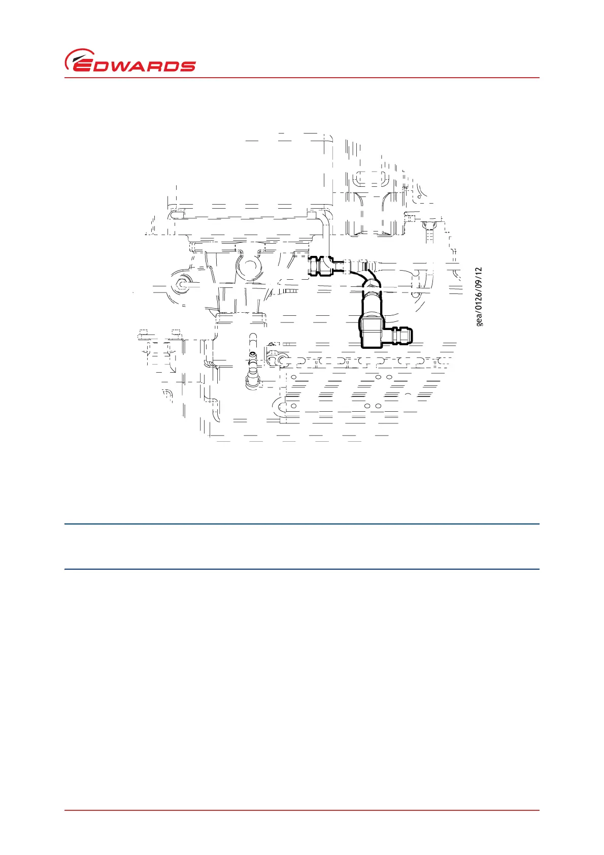
Figure 80 - Pressure transducer assembly installation position - GXS450/750
8.3.5 Electrical connection to the on-pump controller
8.3.5.1 Installation safety
Be sure to route and secure accessory cables as shown to prevent cables from resting on hot surfaces. Accessory
cables may be damaged if they touch the dry pump, booster and spools during pump operation.
The route for the accessory cable inside the GXS enclosure has been chosen carefully to ensure that the cable does
not rest on hot surfaces or pass over other cables carrying mains voltages. When fitting the accessory cable, carefully
follow the instructions given in the sections below. Ensure that cable ties are used as shown to keep the cable in the
correct position.
8.3.5.2 Installing the cables inside the GXS enclosure
1. If the GXS system is running, shut it down.
2. Allow the system to cool sufficiently before moving on to step 3, Minimum one hour.
3. Isolate the GXS system from the electrical supply.
4. Using a suitable screw driver, remove both side panels and store them safely nearby.
5. Refer to Figures 79, 80 and 81 to identify the internal position of the pressure transducer within the pump.
6. Connect the cable to the pressure transducer as shown in Figure 81.